Sol Ark External Limit Sensors And Generator Bypass Guide
Updated 15 September 2026 · By SolarNevs Research Desk, Dealer surveys + verified sources · 2 sources · Method ↗
Key Takeaways
- External limit sensors (CT clamps) manage power flow, often for zero export compliance.
- Generators provide backup power, with the inverter managing their start/stop.
- A bypass interlock kit ensures safe isolation for maintenance or direct power supply.
- Specific Sol-Ark wiring and configuration details are crucial and typically found in the manufacturer's manual.
Understanding Sol-Ark External Limit Sensors (CT Clamps)
External limit sensors, commonly known as Current Transformers (CT clamps), are vital components in many solar photovoltaic (PV) installations, particularly those involving hybrid inverters like Sol-Ark. Their primary function is to monitor the flow of electrical current at specific points within the electrical system. This monitoring allows the inverter to make informed decisions about power generation, consumption, and export.
The core purpose of these sensors is often to manage grid interaction. For instance, in regions with strict grid regulations, a system might be required to achieve "zero export to grid." This means that no excess solar power should be sent back to the utility grid. CT clamps placed on the main utility lines measure the net current flowing in or out of the property. The Sol-Ark inverter uses this data to dynamically adjust its output, ensuring that solar generation matches the home's consumption, preventing any surplus from being exported.
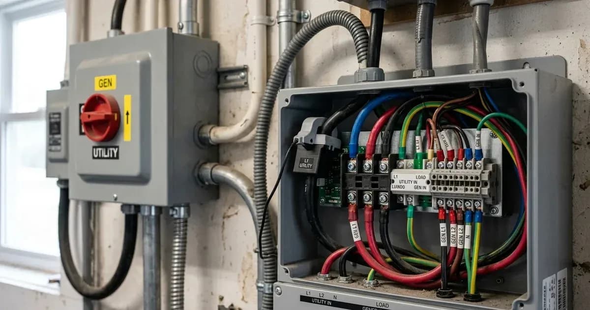
While the specific installation protocols for Sol-Ark CT clamps are detailed in the manufacturer's documentation, the general principle involves placing the split-core sensors around the live conductors. The directional arrow on the sensor indicates the intended flow of current it is measuring, which is critical for the inverter to correctly interpret the data. Incorrect orientation can lead to erroneous readings and improper system behaviour, such as unintended export or import.
Integrating a Standby Generator with Sol-Ark Inverters
For enhanced energy resilience, Sol-Ark inverters are designed to integrate with standby generators. This integration provides an automatic backup power source, ensuring continuous electricity supply during grid outages or when battery storage is depleted. The inverter can manage the generator's operation, including automatic starting and stopping.
The connection of a generator to a Sol-Ark system typically involves dedicated input terminals on the inverter. These terminals allow the inverter to sense the presence of the generator and control its operation. A common method for automatic generator control is a two-wire autostart mechanism. When the inverter detects specific conditions, such as low battery voltage or a grid outage, it sends a signal to the generator to start. Once the grid returns or batteries are recharged, the inverter signals the generator to shut down.
A critical aspect of generator integration is ensuring compatibility, particularly regarding frequency. In Sol-Ark generator setups, it is important to verify the generator frequency range in the inverter's Gen input settings. This range is typically 55Hz to 65Hz. Operating outside this range can lead to instability or damage to the inverter or connected appliances. Proper configuration ensures that the generator's output is stable and within the inverter's operational parameters.
The Role of a Whole-Home Bypass Interlock Kit
A whole-home bypass interlock kit is a safety and maintenance component that allows the entire solar and battery system, including the Sol-Ark inverter, to be safely isolated from the main electrical panel. This is particularly important for situations requiring maintenance on the inverter or other system components, or when utility personnel need to work on the main service.
The interlock mechanism typically prevents the utility grid, the generator, and the inverter from simultaneously supplying power to the home's electrical panel. This ensures that there is no back-feeding of power into the grid during an outage, which is a critical safety requirement for utility workers. It also allows the home to be powered directly by the utility or a generator, bypassing the solar system entirely, without needing to disconnect individual circuits.
Installation of a bypass interlock kit must comply with relevant electrical codes, such as NEC Article 702 for Optional Standby Systems. These codes dictate the safe design and operation of such systems, including requirements for dedicated overcurrent protection devices and proper grounding. A qualified electrician must perform the installation to ensure safety and compliance.
What you can check yourself, and what you cannot
Task / Subsystem | Homeowner Scope (Visual & Monitoring) | Accredited Installer Scope |
|---|---|---|
CT Limit Sensors | Monitor app/screen for unintended grid export | Install split-core clamps and verify directional arrow orientation |
Standby Generator | Confirm autostart behaviour and view frequency | Wire two-wire autostart terminals and set 55Hz–65Hz Gen input window |
Whole-Home Bypass Kit | Verify manual switch position during system bypass | Wire interlock mechanism per NEC 702 and verify isolation barriers |
Grid & Safety Controls | Check overall power flow and battery status | Configure grid-protection thresholds and execute lock-out/tag-out isolation |
Homeowners can perform basic visual checks and monitor system performance through the Sol-Ark's user interface or mobile application. You can observe if the system is exporting power when it should not be, or if the generator is starting and stopping as expected. You can also verify the generator frequency range in the inverter's settings, ensuring it matches the generator's specifications.
However, any physical wiring, connection, or internal configuration changes to the Sol-Ark inverter, CT clamps, generator wiring, or bypass interlock kit must be performed by an accredited installer or a qualified electrician. This includes:
- Installation or re-orientation of CT clamps: Incorrect wiring or placement can lead to inaccurate readings and system malfunction.
- Connecting or disconnecting generator wiring: This involves high voltage and current and requires adherence to specific wiring diagrams and safety protocols.
- Modifying bypass interlock wiring: This is a critical safety component, and any alterations could create hazardous conditions or violate electrical codes.
- Changing advanced inverter settings: While some basic settings might be accessible, critical grid-protection settings are set by an accredited installer to comply with connection agreements. Changing these yourself can breach your agreement and compromise safety.
Always ensure that power is isolated at all relevant breakers (PV, battery, AC utility, generator) and that appropriate lockout/tagout procedures are followed before any work is attempted. An accredited professional understands the complexities of these interconnected systems and can ensure safe and compliant operation.
What the published sources do not tell you
The provided official documentation, while referencing general electrical standards and tax credit information, does not contain specific wiring diagrams, terminal designations, or detailed configuration steps for Sol-Ark external limit sensors, CT clamps, generator autostart functions, or whole-home bypass interlock kits.
Specific operational parameters, such as the exact settings for zero export, peak shaving, or smart load shedding frequency controls, are not detailed. Furthermore, published guidance does not provide information on specific Sol-Ark model numbers, their unique features, or any fault codes related to these components.
For these specific details, installers and homeowners must consult the official Sol-Ark installation manuals, wiring guides, and technical specifications provided directly by the manufacturer. These documents contain the precise instructions, diagrams, and settings required for safe and compliant installation and operation of Sol-Ark products. Network rules that vary by distributor or specific local grid operator requirements are also not covered here and must be obtained from the relevant authorities.
Add a battery at a surveyed price
Installers quote supply and fitting of the battery on this page for your existing or new system.
How this pays for the site: installers pay SolarNevs a fixed introduction fee when we pass them a genuine enquiry. They cannot pay to appear higher, and our surveyed prices are published before any introduction. You can also take our dated price tables straight to any installer.
Frequently asked questions
What are the primary technical requirements for sol ark external limit sensors and generator bypass guide?
Key requirements include compliance with local grid codes, correct equipment certification, and proper electrical isolation.
Who is authorized to install and inspect sol ark external limit sensors and generator bypass guide?
All high-voltage DC, AC grid tie-in, and switchboard modifications must be performed by a qualified, accredited electrical professional.
How is export power limited in sol ark external limit sensors and generator bypass guide?
Export limiting is achieved using certified bidirectional smart meters or power sensors providing dynamic feedback to the inverter system.
References
- NEPRA (Prosumer) Regulations 2026, SRO 251(I)/2026 - manual disconnect with visual break, UL 1741 inverter compliance and agreed voltage/frequency settings at the interconnection point — accessed 6 September 2026
- LESCO Net Metering - interconnection SOPs, single line diagram and list of certified net-metering vendors and installers — accessed 6 September 2026
Related guides
More from what to buy — and how not to get cheated.