Pylontech US2000, US3000C, US5000 DIP Switch Setup for Victron Systems
Updated 6 September 2026 · By SolarNevs Research Desk, Dealer surveys + verified sources · 2 sources · Method ↗
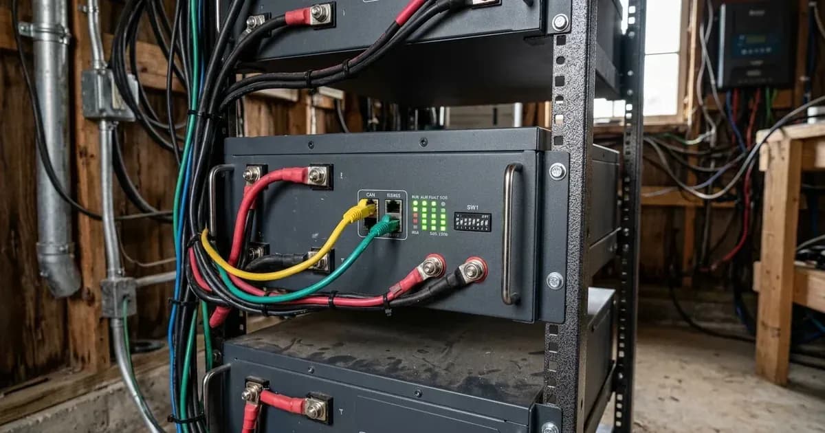
Pylontech low-voltage rack batteries, including the US2000, US3000C, and US5000 series, are popular choices for Victron Energy systems. Correctly configuring their DIP switches and communication settings is crucial for stable operation and proper battery management. This guide details the step-by-step process for setting up these Pylontech batteries with Victron GX devices.
Understanding Pylontech Models and Communication
Pylontech batteries integrate with Victron systems via CAN-bus communication, allowing the battery's internal Battery Management System (BMS) to share critical data and control charging/discharging limits. The models covered in this guide are:
- Pylontech US2000 (Plus/C/D): 48V nominal, 2.4 kWh module capacity.
- Pylontech US3000(C): 48V nominal, 3.5 kWh module capacity.
- Pylontech UP5000 & US5000(B): 48V nominal, 4.8 kWh module capacity.
For a Victron GX device to detect and manage these batteries, specific firmware versions, cabling, and DIP switch settings are required.
Safety First: Working with Battery Systems
Working with battery systems involves significant electrical hazards. Always prioritize safety by following these guidelines:
- Qualified Personnel Only: Configuration, installation, service, and operating tasks should only be performed by qualified personnel.
- Isolate Power: Before making any connections or adjustments, ensure all power sources (PV, AC, and battery) are disconnected and isolated.
- Pre-charge DC Bus: It is essential to pre-charge the DC bus before switching on the battery breaker to prevent huge inrush current and potential damage. This can be achieved by switching on the AC input to inverters or solar panels to MPPTs.
- Firmware Updates: Do not attempt firmware updates using the battery for power until communication is confirmed. If the battery turns off midway through a firmware update, the consequences could be serious.
Step-by-Step Pylontech DIP Switch and Communication Setup
Follow these steps to ensure your Pylontech batteries are correctly configured for your Victron Energy system.
Step 1: Verify Firmware Requirements
Ensure your Victron GX device and VE.Bus products meet the minimum firmware versions for Pylontech compatibility.
- GX Device Firmware: For new systems, the minimum required firmware version for the GX Device (e.g., Cerbo GX) is
v2.42. It is highly recommended to use the latest available firmware. - VE.Bus Firmware: The minimum firmware version for new installations of VE.Bus products (MultiPlus, Quattro) is
469. It is highly recommended to use the latest available firmware.
Step 2: Connect CAN-bus Communication Cable
The correct Victron VE.Can to CAN-bus BMS cable is essential for communication between your Pylontech battery bank and the GX device.
- For US2000C/D, US3000C, UP5000, US5000, US5000B, Force-L: Use the Victron **VE.Can to CAN-bus BMS type A Cable**, part number
ASS030710018. - For US2000, US3000, UP2500: Use the Victron VE.Can to CAN-bus BMS type B Cable, part number
ASS030720018.
Connect one end of the cable to the Pylontech battery's CAN port and the other end to the VE.Can port on your GX device.
Step 3: Configure Pylontech DIP Switches
For most Pylontech installations with Victron GX devices, the DIP switches on the master battery unit must be set to a specific configuration.
- DIP Switch Setting: The address DIP-switches must be set to
000for correct operation. If any other setting is used, the GX device will not detect the battery.
Step 4: Identify the Master Battery Unit
When connecting multiple Pylontech battery modules in parallel, one battery must be designated as the master.
- Master Battery Identification: The battery with the empty link port 0 is the master battery. Multiple battery modules connect via RJ-45 cable using link ports to form a single large battery.
Step 5: Configure GX Device CAN-bus Profile
After physically connecting the battery and setting the DIP switches, configure the GX device to recognize the Pylontech BMS.
- Navigate to the GX device menu: Settings -> Services -> VE.CAN port.
- Select the CAN-bus BMS (500 kbit/s) CAN-profile. The CAN-bus baud rate for BMS-Can communication is
500 kbit/s.
Step 6: Verify DVCC and Shared Sense Settings
Dynamic Voltage and Current Control (DVCC) is crucial for proper battery management in Victron systems with managed batteries.
- DVCC: DVCC will be forced
ONif the GX device runsv2.80+and the Pylontech battery is correctly detected. - Shared Voltage Sense (SVS): This setting will be forced
OFFif the GX device runsv2.80+. - Shared Temperature Sense (STS): This setting will also be forced
OFFif the GX device runsv2.80+.
Step 7: Consider LV-Hub for Large Systems
For larger Pylontech battery banks, additional equipment may be necessary.
- LV-Hub: When using more than
8parallel units, some limitations, additional configuration or equipment (e.g., Pylontech LV-Hub) may apply. Consult Pylontech documentation for specific models and scaling requirements.
Step 8: Minimum Battery Sizing for Inverters
Ensure your Pylontech battery bank is adequately sized for your Victron inverter/charger to prevent issues like unexpected shutdowns due to inrush current or overload. Below are examples for US2000 modules:
Victron Inverter/Charger Model | Minimum US2000 Modules |
|---|---|
Multiplus 48/3000/35 | 2 |
Multiplus 48/5000/70 | 4 |
Quattro 48/8000/110-100/100 | 6 |
Quattro 48/10000/140-100/100 | 7 |
Quattro 48/15000/200-100/100 | 10 |
These minimums are necessary to supply startup inrush surge currents. In off-grid systems, the inverter will prioritize running the load, and potentially exceed the battery's Discharge Current Limit. This could lead to the battery shutting down, highlighting the importance of following minimum battery sizing guidelines.
Troubleshooting Common Pylontech Issues
If you encounter problems after setup, consider these common issues:
- Battery Turns Off Unexpectedly: This can occur if the communication cable is not properly connected or the battery is not showing on the GX device display. Without properly connecting this cable, the battery will not show up on the display of the GX device. The battery will also turn itself off.
- MPPT Error #67: If an MPPT charge controller stops charging and flashes an error code on its LEDs, and the error code is error
#67, it indicates "no BMS" communication. Recheck your CAN-bus cabling and GX device settings. - BMS Triggers Over-Current Alarms: Using very large solar arrays with battery banks that are too small can exceed the limits of the batteries' ability to charge and possibly lead to the BMS triggering over-current alarms.
- High Voltage / Internal Error Alarms: If you experience "High Voltage" or "Internal Error" alarms, you may need to enable "Limit managed battery charge voltage" and adjust the voltage limit down for balancing. Otherwise, this feature should be left OFF.
By following these detailed steps, you can ensure a reliable and efficient integration of your Pylontech US2000, US3000C, or US5000 batteries with your Victron Energy system.
Add a battery at a surveyed price
Installers quote supply and fitting of the battery on this page for your existing or new system.
How this pays for the site: installers pay SolarNevs a fixed introduction fee when we pass them a genuine enquiry. They cannot pay to appear higher, and our surveyed prices are published before any introduction. You can also take our dated price tables straight to any installer.
Frequently asked questions
How do I clear faults on pylontech us2000 us3000c us5000 dip switch setup?
Isolate DC and AC power, wait 5 minutes for internal capacitors to discharge, verify connections, and restart the unit following manufacturer restart sequence.
Are these error codes universal across countries?
Hardware error codes and communication protocols are brand-global, but grid voltage and frequency trip thresholds are governed by regional standards.
References
- Pylontech US Series Operation Manual — accessed 27 August 2026
- Pylon Technologies Technical Integration Guide — accessed 27 August 2026
Related guides
More from what to buy — and how not to get cheated.