Victron Argodiode Battery Isolator Setup and Compensation Wiring Guide
Updated 6 September 2026 · By SolarNevs Research Desk, Dealer surveys + verified sources · 1 source · Method ↗
Key Takeaways
- Always connect the compensation diode to the alternator regulator sense to prevent chronic battery undercharging.
- Victron Argodiode isolators have a voltage drop of approximately 0.3V at low current and 0.45V at rated output.
- AC-designated Argodiode models require the energize terminal to be wired for alternators needing B+ excitation.
- Always isolate power sources and disconnect battery negative cables using insulated tools before installation to avoid short circuits and ensure proper convective cooling.
How do you properly set up and wire a Victron Argodiode battery isolator?
Victron Argodiode battery isolators are engineered to allow simultaneous charging of two or three independent battery banks from a single alternator. This design ensures that accessory or house battery loads do not discharge the engine starter battery, maintaining its readiness. Proper setup involves two critical wiring steps: connecting the compensation diode to offset voltage drop and, for AC models, wiring the current-limited energize terminal to ensure alternator excitation.
Diagnosing Common Argodiode Wiring Issues
Correct installation of a Victron Argodiode isolator is crucial for optimal battery health and system performance. Incorrect wiring, particularly regarding the compensation and energize terminals, can lead to chronic undercharging or a complete failure of the alternator to charge.
Step 1: Check for Chronic Undercharging
Symptom: Your battery banks, especially the house or auxiliary batteries, consistently fail to reach a full state of charge, or their voltage readings are lower than expected when the engine is running. For example, you might observe 13.95V at the battery terminals instead of the expected 14.4V absorption voltage.
What it means: This is a common indicator of an uncompensated voltage drop across the isolator's Schottky diodes. The Argodiode isolators inherently cause a voltage drop of approximately 0.3V at low current and approximately 0.45V at rated output. If the alternator's voltage regulator does not sense this drop, it will not increase its output to compensate, leading to undercharging.
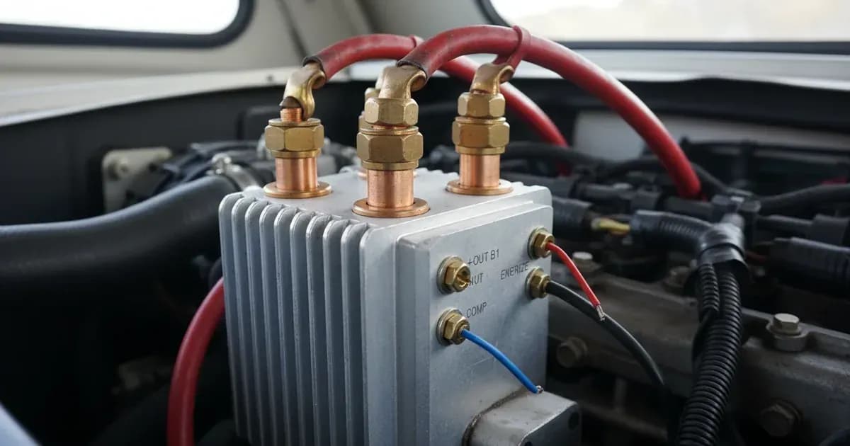
Action: Verify that the compensation diode terminal (a 6.3mm Faston blade) on the Argodiode is correctly connected to the alternator's voltage regulator sense input. This connection tells the alternator to slightly increase its output voltage, offsetting the diode losses.
Step 2: Verify Alternator Excitation
Symptom: The alternator does not begin charging at all when the engine is running, and there is no voltage output from the alternator's main charging terminal (B+).
What it means: Some alternators require an initial DC voltage on their B+ terminal to "excite" them and begin generating power. If you have an AC-designated Argodiode model (e.g., 80-2AC, 100-3AC, 120-2AC, 140-3AC, 160-2AC, or 180-3AC), it includes a special current-limited energize input for this purpose. If this terminal is not wired, the alternator may not start charging.
Action: For AC models, ensure the current-limited energize terminal (another 6.3mm Faston blade) is connected to a switched positive source, typically the engine run/stop switch. This provides the necessary excitation voltage to the alternator when the engine is turned on. SC models (e.g., 80-2SC) do not have this feature and are intended for alternators that self-excite.
Step 3: Inspect Cable Sizing and Connections
Symptom: The Argodiode isolator feels excessively hot to the touch, or you observe significant voltage drop between the alternator and the isolator, or between the isolator and the battery banks.
What it means: This can indicate that the continuous current drawn through the isolator exceeds its maximum rating (which ranges from 80A to 180A depending on the model), or that the DC cables connecting the components are too small in cross-section. Inadequate cable sizing compounds the diode forward drop with resistive losses. Loose or corroded connections also contribute to voltage drop and heat.
Action: Confirm that the total maximum charge current from your alternator does not exceed the Argodiode model's maximum charge current rating. Use appropriately sized heavy-gauge DC cabling for all main power connections to minimize resistive losses. Ensure all connections, particularly to the M6 studs on 80A and 100A models, or M8 studs on 120A, 140A, 160A, and 180A models, are clean, secure, and properly tightened.
Argodiode Troubleshooting and Wiring Guide
Symptom detail | Likely cause | Fix |
|---|---|---|
Battery banks consistently undercharged | Uncompensated Schottky diode voltage drop (approximately 0.3V at low current, approximately 0.45V at rated output) | Connect the compensation diode terminal (6.3mm Faston blade) to the alternator regulator sense input. This allows the alternator to slightly increase its output voltage. |
Alternator fails to start charging (AC models only) | Alternator requires B+ excitation, energize terminal not wired | Connect the current-limited energize terminal (6.3mm Faston blade) to a switched positive source, such as the engine run/stop switch. |
Isolator overheating or excessive voltage drop | Continuous current exceeds model rating (80A to 180A) or inadequate cable sizing | Ensure the total charge current from the alternator is within the Argodiode model's maximum charge current. Use appropriate cable cross-section for all high-current DC connections. |
Loose connections or poor contact at main studs | Vibration, improper installation, or corrosion | Disconnect all power, clean and tighten all main DC connections (M6 studs on 80A/100A models, M8 studs on 120A/140A/160A/180A models). |
Understanding Argodiode Features and Connections
Victron Argodiode battery isolators are solid-state devices designed for robust performance in multi-battery systems. They operate without software configuration or microprocessor programming, making them reliable and straightforward to integrate.
The core technology relies on Schottky diodes, which are chosen for their low forward voltage drop. This drop is approximately 0.3V at low currents and increases to approximately 0.45V at the isolator's full rated output. To counteract this inherent voltage reduction and ensure batteries receive a full charge, all Argodiode models are fitted with a compensation diode. This compensation diode connects via a 6.3mm Faston blade terminal to the alternator's voltage regulator sense circuit. When connected, it signals the alternator to slightly increase its output voltage, effectively boosting it to offset the diode losses.
For alternators that require an initial B+ excitation voltage to begin charging, AC-designated Argodiode models (e.g., 80-2AC, 100-3AC, 120-2AC, 140-3AC, 160-2AC, and 180-3AC) include a special current-limited energize input. This input, also a 6.3mm Faston blade terminal, should be connected to a switched positive source, typically the engine run/stop switch. This provides the necessary voltage to "wake up" the alternator. Models designated with "SC" (e.g., Argodiode 80-2SC) do not have this energize input and are suitable for self-exciting alternators.
Argodiode isolators are compatible with both 12V and 24V DC systems. They are available in various current ratings, with maximum charge currents ranging from 80A to 180A, depending on the model. The number of battery banks supported also varies: -2 models (e.g., 80-2SC, 80-2AC, 120-2AC, 160-2AC) can charge two battery banks, while -3 models (e.g., 100-3AC, 140-3AC, 180-3AC) can charge three. Main DC connections are made via heavy-duty studs: M6 studs are used on 80A and 100A models, while M8 studs are found on 120A, 140A, 160A, and 180A models.
For system-wide DC current and state-of-charge monitoring, Argodiode isolators are compatible with other Victron devices such as the Victron SmartShunt or the Victron Lynx Distributor. You can find more information on integrating these components in our guides: Victron SmartShunt and Lynx Distributor Wiring and Victron Orion-Tr Smart DC-DC Charger and Dual Battery Setup Guide.
Safety: Critical Installation Practices
Working with high-current DC electrical systems requires strict adherence to safety protocols to prevent injury, fire, or damage to equipment.
- Disconnect Power: Always disconnect all battery negative cables before attempting any installation, wiring, or modification of high-current DC isolator connections. This eliminates the risk of accidental short circuits.
- Mounting: Mount the Argodiode isolator vertically on a non-flammable surface. Ensure there is adequate clearance around the unit to allow for natural convective cooling. Overheating can occur if airflow is restricted, especially when operating at the maximum alternator current.
- Common Negative: Ensure all battery negative terminals share a common negative busbar connection. This provides a safe and reliable return path for all electrical currents.
- Insulated Tools: Use insulated tools when tightening or disconnecting terminals to prevent accidental short circuits, particularly across battery terminals or high-current busbars. A spanner across a battery bank can short hundreds of amps, causing severe arcing and burns.
When to call a technician instead
While many Argodiode installation and troubleshooting steps can be performed by a competent DIY enthusiast, there are situations where professional assistance is recommended.
If you are unsure about identifying the correct alternator regulator sense wire, or if your alternator requires specific excitation wiring that is not straightforward, a qualified marine or automotive electrician should be consulted. Similarly, if you suspect internal alternator issues, or if the problem persists after verifying all wiring and connections, a technician can perform advanced diagnostics. Complex system integrations, especially those involving multiple charging sources or advanced monitoring systems, may also benefit from professional expertise to ensure optimal performance and safety.
Add a battery at a surveyed price
Installers quote supply and fitting of the battery on this page for your existing or new system.
How this pays for the site: installers pay SolarNevs a fixed introduction fee when we pass them a genuine enquiry. They cannot pay to appear higher, and our surveyed prices are published before any introduction. You can also take our dated price tables straight to any installer.
Frequently asked questions
What is the purpose of a Victron Argodiode battery isolator?
Victron Argodiode isolators enable simultaneous charging of two or three independent battery banks from a single alternator. They prevent accessory or house battery loads from discharging the engine starter battery, ensuring reliable engine starts.
Why is compensation wiring important for Victron Argodiode isolators?
Argodiode isolators use Schottky diodes, which cause a voltage drop of approximately 0.3V at low current and 0.45V at rated output. Connecting the compensation diode terminal to the alternator's voltage regulator sense circuit slightly increases alternator output voltage, offsetting this drop and preventing chronic battery undercharging.
Which Victron Argodiode models require an alternator energize terminal connection?
AC-designated Argodiode models (e.g., 80-2AC, 100-3AC, 120-2AC, 140-3AC, 160-2AC, 180-3AC) incorporate a current-limited alternator energize terminal. This terminal supplies B+ excitation voltage to alternators that require it to begin charging when the engine run/stop switch is closed.
What is the typical voltage drop across a Victron Argodiode isolator?
The voltage drop across an Argodiode isolator is approximately 0.3V at low currents and increases to approximately 0.45V at the isolator's full rated output. This drop is compensated by proper wiring of the compensation diode.
What are the maximum current ratings for Victron Argodiode isolators?
Victron Argodiode isolators are available with maximum charge current ratings ranging from 80A to 180A, depending on the specific model. These ratings also correspond to the maximum alternator current the unit can handle.
References
- Victron Energy Datasheet - Argodiode Battery Isolators — accessed 23 August 2026
Related guides
More from what to buy — and how not to get cheated.