Fronius GEN24 And BYD Battery Box Premium Setup Guide
Updated 15 September 2026 · By SolarNevs Research Desk, Dealer surveys + verified sources · 2 sources · Method ↗
Key Takeaways
- Modbus RTU communication between the inverter and battery requires shielded twisted-pair cabling.
- The 120-Ohm Modbus termination resistor switch on the Fronius GEN24 communication card must be activated.
- Both the inverter chassis ground and battery metal enclosure require bonding to the main earthing terminal.
- Current Transformer (CT) clamps must be installed with arrows pointing towards household loads.
Setting Up Communication Between Fronius GEN24 and BYD Battery-Box Premium
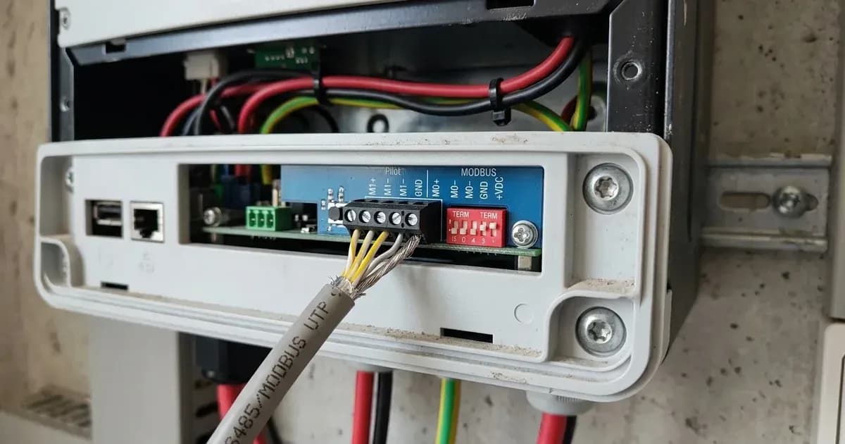
Establishing reliable communication is crucial for your Fronius GEN24 inverter to manage a BYD Battery-Box Premium HVS or HVM system effectively. This communication allows the inverter to monitor battery state, control charging and discharging, and ensure safe operation. The Fronius GEN24 and BYD Battery-Box Premium batteries communicate using Modbus RTU.
This setup requires specific cabling and configuration. The communication link must use "shielded twisted-pair cabling" to maintain signal integrity and prevent interference. Once the physical connection is made, a critical step is to activate the "120-Ohm Modbus termination resistor switch" on the Fronius GEN24 communication card. This resistor is essential for proper signal termination in the Modbus RTU network, preventing signal reflections that can disrupt communication.
The Role of Earthing and Protective Bonding
Proper earthing, also known as grounding, is a fundamental safety requirement for any electrical installation, especially those involving high-voltage battery systems. For your Fronius GEN24 inverter and BYD Battery-Box Premium, it is essential to "bond inverter chassis ground and battery metal enclosure to the main installation earthing terminal."
This protective bonding ensures that in the event of an electrical fault, any exposed metal parts remain at a safe voltage, preventing electric shock. It provides a low-resistance path for fault currents to flow safely to earth, allowing protective devices like circuit breakers to trip and disconnect the supply. This measure complies with international microgeneration safety and grid protection standards.
Current Transformer (CT) Clamp Installation and Troubleshooting
Current Transformer (CT) clamps are vital components that allow your Fronius GEN24 inverter to measure the energy flow within your property. They monitor how much electricity is being consumed by your household loads and how much is being exported to or imported from the grid. Correct installation of these clamps is paramount for accurate system operation.
You must "Install Current Transformer clamps with arrows pointing towards the household loads away from the grid incomer." This orientation ensures that the inverter correctly interprets the direction of current flow. If the CT clamps are installed incorrectly, the system will receive misleading data. For instance, "Negative power flow during high household consumption indicates inverted CT clamp installation." If you observe this, it means the clamp is backward and needs to be reoriented.
CT Clamp Installation Checklist
Step | What to do | Safety Note |
|---|---|---|
1 | Ensure complete AC circuit isolation and lock-out | Always isolate AC power at the main switch and lock it out to prevent accidental re-energisation. |
2 | Identify the grid incomer and household load cables | CT clamps measure current on these specific cables. |
3 | Install CT clamps with arrows pointing towards loads | The arrow on the CT clamp must point in the direction of energy flow to your household appliances. |
4 | Verify correct orientation | Check system monitoring for accurate power flow readings after installation. |
5 | Reorient if negative power flow is observed | If "Negative power flow during high household consumption indicates inverted CT clamp installation," reverse the clamp. |
What You Can Check Yourself, and What You Cannot
As a homeowner, you can perform visual checks and basic monitoring to ensure your system is operating as expected. You can verify that the physical Modbus cable is securely connected and that the CT clamps are oriented correctly based on system readings. If you notice "Negative power flow during high household consumption," you can identify this as a potential CT clamp orientation issue.
However, any work involving opening the inverter enclosure, making or altering electrical connections, or changing internal settings should only be performed by an accredited installer. This includes activating the "120-Ohm Modbus termination resistor switch" on the Fronius GEN24 communication card, which is an internal configuration. Always ensure "complete AC circuit isolation and lock-out before installing CT clamps on live busbars." Working with live electrical components carries a significant risk of electric shock and can damage your equipment. An accredited installer understands the specific requirements for "Main earthing terminal protective bonding" and ensures compliance with all safety standards.
What the Published Sources Do Not Tell You
The provided sources offer high-level statements about compliance and general features but lack specific, step-by-step wiring diagrams, detailed pinouts for Modbus connections, or precise baud rate settings for the RS485 communication. While it mentions to "Maintain shielded twisted-pair cabling and verify proper RS485 communication baud rate settings," it does not specify what those settings should be for the GEN24 and BYD combination.
Furthermore, the documentation does not provide specific fault codes or troubleshooting steps beyond the CT clamp orientation issue. It also does not detail the exact process for using the "Be Connect Plus Configuration App" for commissioning, or how the "ESS assistant dynamically manages battery charge and discharge based on grid tariffs and load" in practice. These details are typically found in manufacturer-specific installation manuals, which are often restricted to certified installers due to the technical complexity and safety implications involved. The precise "Series Modular Battery Tower Stacking" procedures for BYD HVS/HVM are also not elaborated upon.
Add a battery at a surveyed price
Installers quote supply and fitting of the battery on this page for your existing or new system.
How this pays for the site: installers pay SolarNevs a fixed introduction fee when we pass them a genuine enquiry. They cannot pay to appear higher, and our surveyed prices are published before any introduction. You can also take our dated price tables straight to any installer.
Frequently asked questions
What are the primary technical requirements for fronius gen24 and byd battery box premium setup guide?
Key requirements include compliance with local grid codes, correct equipment certification, and proper electrical isolation.
Who is authorized to install and inspect fronius gen24 and byd battery box premium setup guide?
All high-voltage DC, AC grid tie-in, and switchboard modifications must be performed by a qualified, accredited electrical professional.
How is export power limited in fronius gen24 and byd battery box premium setup guide?
Export limiting is achieved using certified bidirectional smart meters or power sensors providing dynamic feedback to the inverter system.
References
- Fronius installation guide - storage solutions: GEN24 Plus with BYD Battery-Box Premium HVS/HVM (commissioning order, BeConnect app) — accessed 15 September 2026
- BYD Battery-Box Premium HVS & HVM compatible inverter list V2.21 (PDF) — accessed 15 September 2026
Related guides
More from what to buy — and how not to get cheated.