Victron VM-3P5A Energy Meter VE.CAN and CT Wiring Guide
Updated 6 September 2026 · By SolarNevs Research Desk, Dealer surveys + verified sources · 1 source · Method ↗
Key Takeaways
- Incorrect current transformer (CT) wiring orientation is a common cause of negative power readings.
- Always verify CT arrow direction and VE.Can bus termination during installation.
- Isolate AC distribution boards and lock out main breakers before any wiring to prevent electric shock.
- Stop DIY installation and consult a qualified electrician if you are unsure about high-voltage AC wiring or persistent issues.
How do you wire and set up the Victron VM-3P5A Energy Meter?
The Victron VM-3P5A Energy Meter, part number REL200320100, is designed for precise AC power flow measurement in high-current three-phase or split-phase systems. It uses external 5A secondary current transformers (CTs) and communicates directly with Victron GX devices via VE.Can or Ethernet, offering plug-and-play operation without manual software configuration.
Diagnosis and Installation Steps
Follow these steps to correctly install and configure your Victron VM-3P5A Energy Meter.
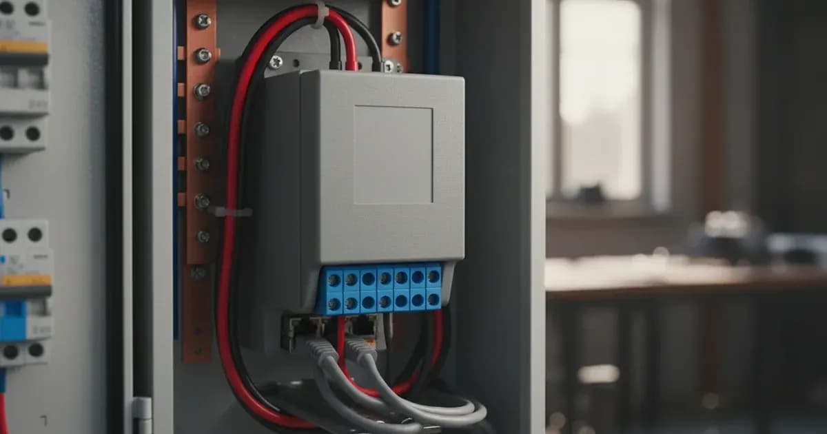
- Mount the VM-3P5A Meter: The VM-3P5A is designed for standard 35mm DIN rail mounting. Choose a secure location within your AC distribution board or enclosure.
- Wire External Current Transformers (CTs): The VM-3P5A requires external 5A secondary current transformers to measure currents exceeding 65A per phase.
- Safety First: Always isolate AC distribution boards and lock out main breakers before installing CTs or any voltage sense taps.
- CT Selection: Ensure your CTs have a 5A secondary output.
- Orientation: Install CTs with the arrow pointing towards the source (e.g., grid, generator) for grid metering, or towards the load for PV inverter or AC load metering. Incorrect orientation causes negative power readings.
- Wiring: Connect the secondary wiring of the CTs to the VM-3P5A's CT input terminals. Use properly insulated twisted-pair cabling to prevent inductive electrical noise.
- Crucial Safety: Never open-circuit the secondary terminals of external current transformers while primary current is flowing. This can induce high voltage spikes across the CT terminals. If you need to disconnect a CT from the meter while the primary circuit is live, always short the CT's secondary terminals first.
- Connect Voltage Reference Taps: Connect the voltage sense wires from L1, L2, and L3 (and Neutral, if applicable) to the VM-3P5A's voltage input terminals. This provides the meter with the necessary voltage reference for power calculations.
- Safety First: Reiterate the importance of isolating AC distribution boards and locking out main breakers before making these connections.
- Establish Communication with a GX Device: The VM-3P5A communicates with Victron GX devices (e.g., Cerbo GX, Ekrano GX) via VE.Can or Ethernet.
- VE.Can Connection: Connect an RJ45 cable from the VM-3P5A's VE.Can port to an available VE.Can port on your GX device. For a simpler and more robust setup, VE.Can offers a direct connection.
- VE.Can Termination: Ensure that 120 Ohm VE.Can bus terminators are installed on the first and last devices in the VE.Can chain. Omitting terminators can introduce communication packet corruption.
- Ethernet Connection: Alternatively, connect an Ethernet cable from the VM-3P5A to your local network, which your GX device is also connected to.
- Plug-and-Play: The VM-3P5A is automatically recognized by Venus OS firmware upon connection without manual setup.
- Verify GX Device Recognition and Status: Once connected, power on your Victron system. Navigate to the device list on your GX device. The VM-3P5A should appear automatically.
- Check for Warnings: Monitor the GX device for any "Incorrect Phase Sequence Warning" messages. If detected, swap the voltage reference connections for the affected phases (L1/L2/L3) at the meter.
- Configure Energy Registration (Optional): The VM-3P5A provides configurable energy registration options.
- Access the meter's settings via your GX device or VRM Portal.
- You can select between Vector, Arithmetic, and Absolute counting. Vector registration is the preferred method in countries such as Germany and Austria, as well as most other regions.
Cause/fix table section
Symptom detail | Likely cause | Fix |
|---|---|---|
Negative power readings or erroneous ESS compensation | Inverted current transformer (CT) orientation (arrow pointing towards load instead of source) | Reorient CTs so the arrow points towards the source (e.g., grid, generator) for grid metering. |
High voltage spikes across CT terminals | Disconnecting CT secondary under live primary load without shorting blocks | Always short CT secondary terminals before disconnecting from meter, or isolate primary AC power. |
Communication packet corruption on VE.Can | Missing VE.Can bus terminators on the last device in the chain | Ensure 120 Ohm terminators are on the first and last devices in the VE.Can chain. |
Network Communication Loss (Ethernet) | Local network router downtime | Check the status of your local network router. The ESS automatically switches to idle passthrough mode. |
Incorrect Phase Sequence Warning on GX device | Reversed phases on L1/L2/L3 voltage reference connections | Swap voltage reference connections for the affected phases (L1/L2/L3) at the VM-3P5A. |
Advanced Meter Configuration and Operation
The Victron VM-3P5A Energy Meter offers robust features for comprehensive energy monitoring in complex systems.
CT Selection and Installation
The VM-3P5A is specifically designed for high-current applications where integrated CTs are insufficient. It supports external current transformers with a 5A secondary output. This allows it to measure AC power flows in three-phase and split-phase systems exceeding 65A per phase. Proper installation of these CTs is critical for accurate readings. Ensure the CTs are correctly sized for your application and that their orientation (arrow direction) aligns with the intended measurement point (source or load).
Communication Setup
The meter's communication flexibility is a key advantage. It offers both VE.Can and Ethernet RJ45 interfaces.
- VE.Can: This provides a direct, robust connection to your Victron GX device, independent of your local network infrastructure. This setup is often preferred for its simplicity and reliability, as it requires zero manual software configuration. Remember to correctly terminate the VE.Can bus.
- Ethernet: For systems integrated into a larger network, the Ethernet connection allows the VM-3P5A to communicate with the GX device and transmit data to the Victron Remote Management (VRM) Portal. In either case, the meter functions plug-and-play, automatically recognized by the Venus OS firmware running on your GX device.
Advanced Settings and Reporting
The VM-3P5A provides real-time data and configurable options to meet various grid standards and monitoring needs:
- Register Refresh Rate: It boasts an ultra-fast 100ms update rate, crucial for instantaneous ESS dynamic zero-export and precise phase balancing.
- Energy Registration Options: You can configure the energy registration algorithm between Vector, Arithmetic, and Absolute counting. Vector registration is commonly used in regions like Germany and Austria.
- Power Factor Reporting: The meter offers real-time per-phase power factor calculation and reporting, visible on your GX console and the VRM Portal.
- Phase Sequence Detection: Active phase rotation monitoring and verification help identify and alert you to incorrect phase sequencing.
Safety: High Voltage AC Wiring Precautions
Working with AC distribution boards and high-current circuits carries significant risks. Adhere strictly to these safety guidelines:
- Isolate Power: Always isolate AC distribution boards and lock out main breakers before installing voltage sense taps, current transformers (CTs), or performing any wiring. Verify zero voltage with a multimeter before proceeding.
- CT Secondary Circuits: Never open-circuit the secondary terminals of external current transformers while primary current is flowing. This can induce extremely high voltage spikes, posing a severe shock hazard and potentially damaging equipment. Always short the secondary terminals if a CT must be disconnected from the meter while the primary circuit is live.
- Insulated Wiring: Connect CT secondary wiring using properly insulated twisted-pair cabling to prevent inductive electrical noise and ensure safety.
- Insulated Tools: Use only insulated tools when working near live electrical components.
- Short Circuit Risk: Be aware that a spanner or other metal tool dropped across live terminals can create a short circuit, leading to severe arcing, burns, and equipment damage.
When to call a technician instead
While this guide covers the installation and basic troubleshooting of the Victron VM-3P5A, certain situations warrant professional assistance:
- Persistent Phase Sequence Issues: If the "Incorrect Phase Sequence Warning" persists after you have carefully swapped voltage reference connections and re-checked wiring.
- Complex AC Distribution Modifications: If the installation requires significant modifications to your main AC distribution board beyond simple CT and voltage tap connections, or if you are unsure about local electrical codes.
- Unresolved Communication Faults: If communication issues with your GX device persist after verifying VE.Can termination, cable integrity, and Ethernet connectivity.
- High Voltage Discomfort: Any task involving high voltage AC wiring that you are not fully comfortable or qualified to handle should be performed by a certified electrician or Victron Energy installer.
- Warranty Concerns: Improper installation can void your product warranty. If in doubt, consult a professional.
Add a battery at a surveyed price
Installers quote supply and fitting of the battery on this page for your existing or new system.
How this pays for the site: installers pay SolarNevs a fixed introduction fee when we pass them a genuine enquiry. They cannot pay to appear higher, and our surveyed prices are published before any introduction. You can also take our dated price tables straight to any installer.
Frequently asked questions
What is the Victron VM-3P5A Energy Meter used for?
The Victron VM-3P5A (Part number: REL200320100) is engineered for three-phase and split-phase energy storage systems, large commercial solar installations, or AC generator power hubs. It measures AC power flows in various applications, including PV inverter output, AC Genset, or as a Grid Meter in an ESS installation.
How does the VM-3P5A connect to a Victron GX device?
The VM-3P5A connects to Victron GX devices (such as Cerbo GX, Ekrano GX) via built-in VE.Can (RJ45) or Ethernet interfaces. It operates plug-and-play, automatically recognized by Venus OS firmware upon VE.Can connection without manual setup.
What type of current transformers does the VM-3P5A use?
The VM-3P5A interfaces with external 5A secondary current transformers (CTs) to measure AC power flows. This allows it to support currents exceeding 65A per phase in both split-phase and three-phase configurations.
What happens if current transformers (CTs) are wired incorrectly?
Installing current transformers with an inverted orientation (arrow pointing toward the load instead of the source) causes negative power readings and erroneous ESS compensation. The GX device may also display a phase rotation alert if phase sequence reporting detects reversed phases.
What safety precautions are needed when installing the VM-3P5A?
Always isolate AC distribution boards and lock out main breakers before installing voltage sense taps or CTs. Never open-circuit the secondary terminals of external current transformers while primary current is flowing, as this can induce high voltage spikes. Connect CT secondary wiring using properly insulated twisted-pair cabling.
References
- Victron Energy Datasheet - Energy Meters selection guide — accessed 23 August 2026
Related guides
More from what to buy — and how not to get cheated.