Victron Argofet Battery Isolator Setup and Alternator Wiring Guide
Updated 6 September 2026 · By SolarNevs Research Desk, Dealer surveys + verified sources · 2 sources · Method ↗
Key Takeaways
- Victron Argofet isolators use Field-Effect Transistor (FET) technology to minimize voltage drop, typically less than 0.02V at low currents and an average of 0.1V at higher currents.
- The 'Energize' terminal must be correctly wired to the engine run/stop switch for modern alternators to begin charging.
- Always mount the Argofet on a non-flammable vertical surface to ensure proper heat dissipation and prevent fire hazards.
- Use appropriately sized heavy-gauge cabling for all main DC connections to avoid significant voltage loss, which can undermine the isolator's efficiency.
How do I install and wire a Victron Argofet Battery Isolator for multi-bank charging?
The Victron Argofet Battery Isolator allows you to charge two or three independent battery banks simultaneously from a single alternator or battery charger. Correct installation involves secure mounting, proper DC wiring using M8 bolts, and connecting the 'Energize' terminal to the alternator for excitation. This setup ensures efficient power distribution with minimal voltage loss.
Diagnosis and Installation Steps
Follow these steps to correctly install and wire your Victron Argofet Battery Isolator and troubleshoot common issues.
- Prepare for Installation:
- Safety First: Before beginning any electrical work, always disconnect all battery negative cables. This prevents accidental short circuits and protects you from electrical shock.
- Mounting Location: Select a suitable mounting location. The Argofet must be mounted on a non-flammable vertical surface. This allows for natural convective heat dissipation, which is crucial during sustained maximum current operation.
- Cable Sizing: Determine the correct cable cross-section for your main DC connections. Inadequate cable sizing can lead to significant voltage drop, negating the Argofet's low-loss design. For example, a current of 50 A through a 10 mm² cable over 5 meters can result in a voltage drop of 0.35 Volt. For 100 A models, a 50 mm² cable over 10 meters will have a voltage drop of 0.26 Volt.
- Connect Main DC Cables:
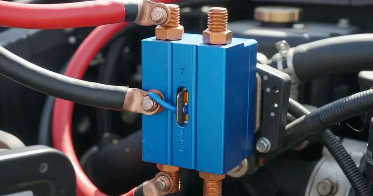
- Input Connection: Connect the main positive cable from your alternator or battery charger to the input terminal of the Argofet. All Argofet models use heavy-duty M8 bolts for these connections.
- Output Connections: Connect the positive cables from each of your battery banks to the corresponding output terminals on the Argofet. The Argofet 100-2 and 200-2 models have 2 battery bank outputs, while the Argofet 100-3 and 200-3 models have 3 battery bank outputs. Ensure all connections are tight and secure.
- Wire the Alternator 'Energize' Terminal:
- Purpose: Modern alternators with internal voltage regulators often require an initial DC excitation voltage on their B+ terminal to start charging. Without this, the alternator will fail to produce output.
- Connection: Connect the 'Energize' blade terminal (a 6.3mm Faston blade terminal) on the Argofet to your engine run/stop switch. This ensures the alternator receives excitation when the engine is running. Use a minimum cable cross-section of 2.5 mm² for this connection.
- Troubleshooting: If your alternator is not charging, verify this 'Energize' connection first.
- Connect the 'Ground' Terminal:
- Common Negative: Connect the 'Ground' blade terminal (a 6.3mm Faston blade terminal) of the Argofet to your common negative busbar. Ensure all battery negative terminals are also connected to this common negative busbar. Use a minimum cable cross-section of 2.5 mm² for this connection.
- Safety: Always ensure all battery negative cables are connected to a common negative busbar for proper system grounding and safety.
- Verify Operation:
- System Voltage: The Argofet automatically adjusts to a 12V or 24V nominal DC system. No manual configuration is needed for voltage selection.
- Blue LED Indicator: Once input voltage is present on the Argofet, the blue LED will illuminate. This confirms the unit is receiving power from the alternator or charger.
- Monitor Charging: Use a battery monitor, such as a Victron SmartShunt or Victron Lynx Distributor, installed on individual battery negative returns to observe charging performance and battery state of charge.
Common Issues and Solutions
Symptom detail | Likely cause | Fix |
|---|---|---|
Alternator not charging any battery banks | Alternator 'Energize' terminal not connected or incorrectly wired | Connect the 'Energize' blade terminal to the engine run/stop switch with a minimum 2.5 mm² cable. |
Low charging voltage at battery banks, despite alternator output | Inadequate cable cross-section between alternator/Argofet and batteries | Use heavier gauge cables. For example, a 50 mm² cable for 100A over 10m, or a 10 mm² cable for 50A over 5m. |
Argofet unit becomes excessively hot during operation | Improper mounting location or insufficient ventilation | Mount the Argofet on a non-flammable vertical surface to allow natural convective heat dissipation. |
Blue LED on Argofet does not illuminate | No DC voltage present on the input terminal of the Argofet | Check connections from the alternator or charger to the Argofet input. |
Argofet Features and Specifications
The Victron Argofet Battery Isolator is designed for robust performance in marine, RV, and off-grid applications. It eliminates the need to increase alternator output voltage, a common requirement with traditional diode isolators.
- FET Technology: Unlike conventional diode isolators that have a 0.3V to 0.6V diode forward voltage drop, Argofet devices use Field-Effect Transistors (FETs). This results in a voltage drop of less than 0.02 Volt at low currents and an average of 0.1 Volt at higher currents.
- Automatic Voltage Sensing: The Argofet automatically adjusts to both 12V and 24V nominal DC systems.
- Models and Capacity:
- Argofet 100-2 / 100-3: Maximum Charge Current of 100A, Maximum Alternator Current of 100A.
- Argofet 200-2 / 200-3: Maximum Charge Current of 200A, Maximum Alternator Current of 200A.
- The '-2' models support 2 battery banks, and the '-3' models support 3 battery banks.
- Connections: All main DC connections utilize heavy-duty M8 bolts. The 'Energize' and 'Ground' terminals are 6.3mm Faston blade terminals, requiring a minimum 2.5 mm² cable.
- Physical Characteristics: All four models (100-2, 100-3, 200-2, 200-3) share the same enclosure dimensions of 65 x 120 x 200 mm (2.6 x 4.7 x 7.9 inches) and weigh 1.4 kg (3.1 lbs).
Safety: Electrical Installation and Heat Management
Working with high-current DC systems requires strict adherence to safety protocols.
- Disconnect Power: Always disconnect battery negative cables before installing or modifying any electrical connections. This prevents accidental short circuits and reduces the risk of electrical shock.
- Proper Grounding: Ensure all battery negative terminals and the Argofet 'Ground' terminal are connected to a common negative busbar. Proper grounding is essential for system stability and safety.
- Mounting Surface: Mount the Argofet exclusively on non-flammable vertical surfaces. The unit generates heat during operation, especially under maximum current loads. A vertical, non-flammable mounting surface allows for natural convective cooling and prevents fire hazards.
- Cable Protection: Protect all cables from chafing, sharp edges, and excessive heat. Use appropriate cable glands and conduits where necessary.
- Insulated Tools: Use insulated tools when working with electrical connections to prevent accidental short circuits. A spanner across a battery bank can short hundreds of amps, causing severe burns or explosions.
When to call a technician instead
While many Argofet installation steps are straightforward, certain situations warrant professional assistance. If you are unsure about cable sizing for your specific application, the correct connection point for your alternator's 'Energize' terminal, or if you encounter persistent charging issues after following the troubleshooting steps, it is best to consult a qualified marine, RV, or automotive electrical technician. Incorrect wiring can damage your electrical system, batteries, or the Argofet unit itself. There are no specific warranty-void warnings listed for incorrect installation, but improper wiring can lead to component failure not covered under standard warranty terms.
Add a battery at a surveyed price
Installers quote supply and fitting of the battery on this page for your existing or new system.
How this pays for the site: installers pay SolarNevs a fixed introduction fee when we pass them a genuine enquiry. They cannot pay to appear higher, and our surveyed prices are published before any introduction. You can also take our dated price tables straight to any installer.
Frequently asked questions
What is a Victron Argofet Battery Isolator?
A Victron Argofet Battery Isolator allows simultaneous charging of two or three independent battery banks from a single alternator or battery charger. It uses Field-Effect Transistors (FETs) to achieve a very low voltage drop, typically less than 0.02V at low currents and an average of 0.1V at higher currents, unlike traditional diode isolators.
What is the typical voltage drop across a Victron Argofet isolator?
The voltage drop across an Argofet isolator is less than 0.02 Volt at low currents. At higher currents, the voltage drop averages 0.1 Volt. This minimal voltage loss helps maintain efficient charging without requiring an increase in alternator output voltage.
How do I connect the alternator to the Argofet isolator?
For modern alternators that require excitation, connect the 'Energize' blade terminal of the Argofet to the engine run/stop switch. This provides the necessary DC excitation voltage to the alternator's B+ terminal, enabling it to begin charging. Use a minimum 2.5 mm² cable for this connection.
What Victron Argofet models are available?
Victron offers Argofet models for 100A and 200A maximum charge currents, each available for either two or three battery banks. Examples include the Argofet 100-2 (100A, 2 banks) and Argofet 200-3 (200A, 3 banks). All models feature M8 bolts for main DC connections and automatically adjust to 12V or 24V nominal DC systems.
Does the Victron Argofet isolator require software configuration?
No, the Victron Argofet isolator operates autonomously with zero software configuration required. It automatically adjusts to 12V or 24V nominal DC systems. A blue LED illuminates to provide instantaneous confirmation of input voltage presence.
References
- Datasheet-Argofet-Battery-Isolators-with-alternator-energize-input-EN-.pdf — accessed 23 August 2026
- Manual-Argofet-EN-NL-FR-DE-IT-ES-SE-TR.pdf — accessed 23 August 2026
Related guides
More from what to buy — and how not to get cheated.