Victron Buck-Boost DC-DC Converter Setup and Smart Alternator Wiring Guide
Updated 6 September 2026 · By SolarNevs Research Desk, Dealer surveys + verified sources · 1 source · Method ↗
Key Takeaways
- The Victron Buck-Boost converter stabilizes variable voltage from Euro 5/6 smart alternators to protect and charge auxiliary batteries.
- Always check the LED indicators first for immediate diagnostic feedback on input voltage, temperature, or battery status.
- Before any wiring, isolate power sources and disconnect battery negative cables using insulated tools to prevent accidental short circuits or electrical shock.
- Stop DIY troubleshooting and consult a technician if the converter repeatedly enters over-temperature shutdown or if complex CAN bus integration is required.
How do I set up a Victron Buck-Boost DC-DC converter for a smart alternator?
The Victron Buck-Boost DC-DC converter is engineered to provide fully regulated DC charging to your 12V or 24V auxiliary service batteries, specifically addressing the variable output voltages from modern smart alternators found in Euro 5 and Euro 6 vehicles. Setup primarily involves correct wiring, mounting, and programming via the Victron Power Discovery PC application.
The converter eliminates destructive high-voltage spikes, such as Mercedes 15.4V peaks, and compensates for insufficient low-voltage periods. This ensures your auxiliary battery receives stable, preset absorption and float voltages for optimal charging and lifespan.
Diagnosis section: Understanding Victron Buck-Boost LED Indicators
The Victron Buck-Boost DC-DC converter uses dual-color status LEDs to provide instant diagnostic feedback. Observing these indicators can help you quickly identify the converter's operational status or the presence of a fault.
- Input LED Yellow: This indicates that the input voltage is below the threshold, specifically below 10V, and the converter is off. Check the starter battery voltage and the alternator output.
- Input LED Red: An Input LED Red light signifies that an over-temperature condition has been detected. The converter automatically turns off to protect its internal power stages. Ensure adequate ventilation and check for obstructions around the unit.
- Input LED Blue Quick Flash: A quick blue flash on the Input LED means the engine running condition has been detected. The converter will initiate charging after a preset timer delay, allowing the starter battery to recover first.
- Input LED Blue Slow Flash: If the Input LED flashes blue slowly, the converter is off, and activation is blocked due to low input voltage. This often occurs if the starter battery voltage is too low to safely begin charging.
- Output LED Yellow: An Output LED Yellow indicates that the converter is off because the battery voltage is low. This suggests the auxiliary battery is deeply discharged or has a fault.
- Output LED Red: An Output LED Red light means the converter is off, and the auxiliary battery is either discharged or not connected. Verify battery connections and check the battery's state of charge.
- Output LED Purple: A solid Output LED Purple indicates that the converter is actively operating and charging the auxiliary battery. This is the normal operational state during charging.
Cause/fix table section: Common Issues and Solutions
Symptom detail | Likely cause | Fix |
|---|---|---|
Input LED Yellow | Input voltage below 10V threshold | Check starter battery voltage; ensure alternator is functioning correctly. |
Input LED Red | Over-temperature detected | Ensure adequate airflow around the converter; relocate if necessary to a cooler, ventilated space. |
Input LED Blue Slow Flash | Low input voltage blocking activation | Allow starter battery to charge more, or check for excessive loads on the starter battery. |
Output LED Yellow | Auxiliary battery voltage low | Check auxiliary battery state of charge; ensure it is properly connected. |
Output LED Red | Auxiliary battery discharged or not connected | Verify all output wiring to the auxiliary battery; test auxiliary battery voltage. |
Alternator over-temperature or overload | Charge current set too high for alternator capacity | Reduce the maximum charge current setting using the Victron Power Discovery PC application. |
False engine running detection or failure to trigger | Incorrect vibration sensor sensitivity or improper threshold calibration | Adjust vibration sensor sensitivity or voltage thresholds via the PC application. |
Undervoltage shutdown during engine cranking | Starter battery voltage drops below 10V under high load | Ensure starter battery is healthy; consider a larger starter battery or reducing other loads during cranking. |
Configuring Your Victron Buck-Boost Converter
The Victron Buck-Boost DC-DC converter offers extensive programmability to suit various vehicle and battery setups. This section outlines the key configuration steps and considerations.
Initial Setup and Wiring Considerations
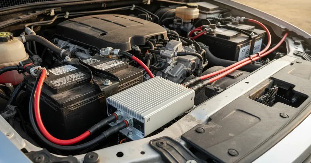
Before any electrical connections, always disconnect battery negative cables to prevent accidental shorts and ensure safety. You must ensure properly rated fuses are installed on both input and output cables, placed as close as possible to the battery terminals. Mount the converter in a dry, well-ventilated location that allows adequate airflow for thermal dissipation, especially for the 100A model which weighs 4.1 kg and measures 288 x 162 x 95 mm. The operating temperature range for all models is -25°C to +60°C, and they can deliver maximum rated current up to 60°C ambient temperature.
Programming with Victron Power Discovery PC Application
Full parameter programming for the Buck-Boost converter is achieved using the Victron Power Discovery PC application. You will need a USB Type-A male to USB Type-B male cable to connect the converter to your computer. This application allows you to customize charge current limits, input current limits, and temperature thresholds. This level of customization is crucial for optimizing charging performance and protecting both your auxiliary battery and the vehicle's alternator.
Engine Running Detection Methods
The Buck-Boost converter features multiple methods for detecting when the engine is running, ensuring it only charges when appropriate.
- Internal Vibration/Motion Sensors: The converter has built-in sensors that detect engine vibration. Sensitivity can be adjusted via the PC application.
- Input Voltage Threshold Algorithms: The converter monitors the input voltage from the starter battery. When the voltage rises above a certain threshold (e.g., indicating alternator output), it triggers charging.
- External Programmable Inputs:
- D+ Connection: A common method for older vehicles, connecting to the alternator's D+ terminal.
- CAN Bus: The 50A and 100A models include a CAN bus interface for advanced network synchronization and engine running detection, which the 25A model does not feature.
- (+)15 Ignition Switch: Connecting to the vehicle's ignition switch, which provides a (+)15 signal when the ignition is on. The "On" threshold voltage for Pin 1 is > 2V, with a maximum input voltage of 30V.
Setting Charge Parameters
The Buck-Boost converter allows you to precisely control the charging process.
- Input Voltage Operating Range: All models operate with an input voltage range of 10V to 30V DC. The under voltage protection threshold is set at 10V by default.
- Output Voltage Regulation Range: The output voltage is fully adjustable from 10V to 30V DC, allowing you to set precise absorption and float voltages for your specific battery chemistry.
- Maximum Charge Current:
- Buck-Boost 25A: Provides 25A at 12V output; 15A at 24V output.
- Buck-Boost 50A: Delivers 50A at 12V output; 25A at 24V output.
- Buck-Boost 100A: Offers 100A at 12V output; 50A at 24V output. It is important to set the charge current appropriate for your auxiliary battery's capacity and the continuous output capacity of your vehicle's alternator to prevent alternator over-temperature or overload.
For more advanced DC system integration, consider reviewing guides on the Victron SmartShunt and Lynx Distributor Wiring or the Victron Lynx Distributor and Modular DC Busbar Wiring Guide. If you are considering other DC-DC charging solutions, our Victron Orion-Tr Smart DC-DC Charger and Dual Battery Setup Guide may also be helpful.
Safety: Essential Precautions for DC-DC Converter Installation
Working with high-current DC systems requires strict adherence to safety protocols. Always disconnect battery negative cables before installing or servicing high-current DC converter connections. This prevents accidental short circuits that can cause severe injury or equipment damage. Ensure properly rated fuses are installed on both input and output cables, positioned as close as possible to the battery terminals. These fuses protect the wiring and equipment from overcurrents. Mount the converter in a dry, ventilated location, allowing adequate airflow for high-current thermal dissipation. Overheating can damage the unit and pose a fire risk.
When to call a technician instead
While many setup and troubleshooting steps can be performed by a competent DIYer, there are situations where professional assistance is recommended. If you experience persistent fault conditions after performing basic checks, such as repeated over-temperature shutdowns despite adequate ventilation, it may indicate an internal fault requiring professional diagnosis. For complex installations involving CAN bus integration on 50A and 100A models, especially with advanced vehicle systems, a qualified technician can ensure correct configuration and avoid potential conflicts with vehicle electronics. If you are unsure about wiring diagrams, fuse sizing, or programming parameters, consulting a professional can prevent damage to your equipment and ensure safe operation.
Add a battery at a surveyed price
Installers quote supply and fitting of the battery on this page for your existing or new system.
How this pays for the site: installers pay SolarNevs a fixed introduction fee when we pass them a genuine enquiry. They cannot pay to appear higher, and our surveyed prices are published before any introduction. You can also take our dated price tables straight to any installer.
Frequently asked questions
What is the purpose of a Victron Buck-Boost DC-DC converter?
The Victron Buck-Boost DC-DC converter provides regulated DC charging to auxiliary service batteries from vehicles with smart alternators. It converts variable input voltages, such as those from Euro 5 and Euro 6 vehicles, into stable absorption and float voltages for your battery bank.
How do I program the Victron Buck-Boost DC-DC converter settings?
Full customization of charge current limits, input current limits, and temperature thresholds is achieved via a USB Type-A to Type-B connection. You use the Victron Power Discovery PC application to configure these parameters.
What input voltage range does the Victron Buck-Boost converter accept?
Across all models, the Victron Buck-Boost DC-DC converter operates within an input voltage range of 10V to 30V DC. The default undervoltage cutoff threshold is 10V.
How does the Victron Buck-Boost detect if the engine is running?
The device incorporates built-in engine running detection through internal vibration/motion sensors and input voltage threshold algorithms. It can also be activated externally via programmable inputs including D+, CAN bus (on 50A and 100A models), or (+)15 ignition switch connections.
What are the maximum charge currents for the different Victron Buck-Boost models?
The 25A model provides 25A at 12V output or 15A at 24V output. The 50A model delivers 50A at 12V output or 25A at 24V output. The 100A model offers 100A at 12V output or 50A at 24V output.
References
- Datasheet-Buck-Boost-DC-DC-converter-25A-50A-100A-EN.pdf — accessed 23 August 2026
Related guides
More from what to buy — and how not to get cheated.