Victron BMV-712 Smart Battery Monitor: Setup & Relay Guide
Updated 6 September 2026 · By SolarNevs Research Desk, Dealer surveys + verified sources · 1 source · Method ↗
Key Takeaways
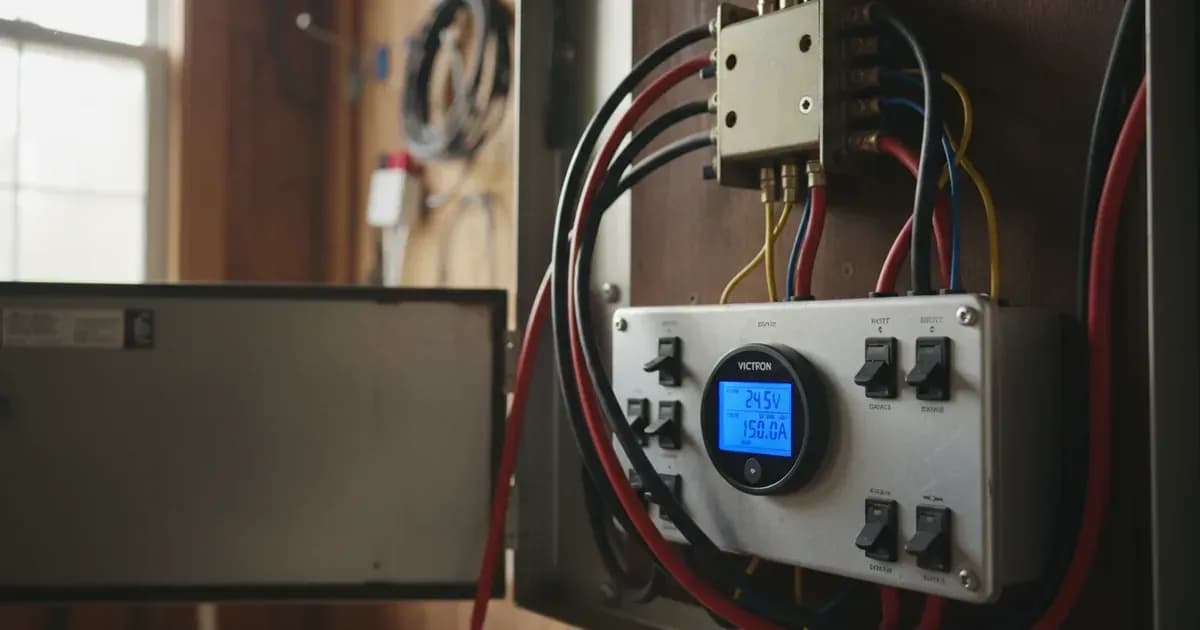
- The Victron BMV-712 Smart combines a high-precision LCD display head unit with a 60V / 1A bistable dry-contact programmable relay.
- Provides high metering precision: 0.01V voltage, 0.01A current, 0.1Ah consumed capacity, 0.1% State of Charge, and 1 min time-to-go.
- The programmable relay supports Default (DFLT), Charger (CHRG), and Remote (REM via VE.Direct) operational modes.
- Setting 14 (Relay minimum closed time) prevents generator short-cycling by enforcing a minimum runtime window upon autostart.
- Auxiliary terminal supports secondary starter battery monitoring, series midpoint balance detection in 24V and 48V battery banks, or temperature sensor inputs.
BMV-712 Hardware Architecture & Display Resolution
The Victron BMV-712 Smart incorporates a 52mm circular LCD head unit connected to a 500A/50mV shunt resistor. Built-in Bluetooth allows setup via the VictronConnect app or directly using the front pushbuttons.
The instrument delivers laboratory-grade measurement precision across core battery metrics:
Metric Displayed | Head Unit Resolution | Measurement Tolerance / Specification |
|---|---|---|
Battery Voltage | 0.01V | High-precision decimal tracking |
Current Flow | 0.01A | Current measurement accuracy ± 0.4% |
Consumed Energy | 0.1Ah | Continuous integration of charge / discharge Ah |
State of Charge (SoC) | 0.1% | 0% to 100% display range |
Time-to-Go | 1 min | Dynamic moving-average runtime estimation |
Programmable Relay Operation & Generator Autostart
Located on the back of the head unit, three terminals provide access to the internal bistable relay: COM (common), NO (normally open), and NC (normally closed).
Under Section 7.3 of the BMV-712 manual, relay behavior is configured across several key modes:
- DFLT (Default Mode): Relay state is governed by configurable battery parameters, including Low SoC, low/high voltage, and midpoint deviation.
- CHRG (Charger Mode): Closes relay to activate external battery chargers when SoC drops below set thresholds.
- REM (Remote Mode): Direct control via the VE.Direct communication port by an external GX supervisory device.
Relay Parameter | Setting Code | Operational Function |
|---|---|---|
Invert Relay | Setting 12 | Selects between normally de-energised (open) and normally energised (closed) contacts |
Minimum Closed Time | Setting 14 | Enforces minimum contact closure duration to prevent short-cycling generator engines |
Low SoC Set Relay | Setting 16 | SoC percentage threshold that energises/closes relay |
Low SoC Clear Relay | Setting 17 | SoC percentage threshold that de-energises/opens relay |
Auxiliary Input Wiring & Midpoint Monitoring
The auxiliary input terminal (AUX) on the BMV-712 shunt PCB enables secondary telemetry:
- Starter Battery Voltage: Monitors auxiliary engine or generator starting batteries.
- Midpoint Voltage: Measures voltage at the center of series battery strings in 24V and 48V battery banks (Section 9.1) to detect cell degradation before thermal runaway occurs.
- Temperature Sensor: Connects a temperature sensor for automatic temperature compensation.
Add a battery at a surveyed price
Installers quote supply and fitting of the battery on this page for your existing or new system.
How this pays for the site: installers pay SolarNevs a fixed introduction fee when we pass them a genuine enquiry. They cannot pay to appear higher, and our surveyed prices are published before any introduction. You can also take our dated price tables straight to any installer.
Frequently asked questions
What is the electrical rating of the programmable relay in the Victron BMV-712 Smart?
The BMV-712 features an integrated bistable dry-contact relay rated at **60V / 1A** with normally open (NO) and normally closed (NC) contacts on the rear of the head unit (August 2026).
What display resolution does the BMV-712 head unit provide?
The head unit displays voltage with **0.01V** resolution, current with **0.01A** resolution, consumed amp-hours with **0.1Ah** resolution, state of charge with **0.1%** resolution, and time-to-go with **1 min** precision (August 2026).
How does the Low State of Charge (SoC) relay function operate?
Under Section 7.3.6, the relay closes when the battery SoC percentage falls below the programmed 'set relay' value and opens when SoC rises above the 'clear relay' value (August 2026).
What is the purpose of the Relay Minimum Closed Time parameter?
Setting 14 (Relay minimum closed time) defines the minimum duration the relay contact remains closed after energisation, commonly used to ensure minimum runtime for auto-start generators (August 2026).
References
- Victron Energy: BMV-712 Smart Manual — accessed 31 August 2026
Related guides
More from what to buy — and how not to get cheated.