Fixing Deye Inverter Parallel Operation Errors
Updated 6 September 2026 · By SolarNevs Research Desk, Dealer surveys + verified sources · 3 sources · Method ↗
Key Takeaways
- The most likely causes for Deye parallel operation errors are incorrect communication wiring or improper settings.
- Your first check should always be the physical CANBus cable connections and the DIP switch configuration on each inverter.
- Always disconnect all AC and DC power sources to all inverters before inspecting or modifying any wiring to prevent electrical shock.
- If errors persist after verifying all physical connections and software settings, contact a qualified technician.
Why is my Deye inverter showing parallel operation errors?
Deye inverters in a parallel configuration can display errors like F29 or F41 due to issues with communication, wiring, or incorrect settings. The most common causes are incorrect CANBus wiring, improper DIP switch settings, or misconfigured parallel settings on the inverter's LCD. Start by checking the physical communication cables between your inverters.
Diagnosing Deye Parallel Operation Errors
Follow these steps to diagnose common parallel operation issues with your Deye hybrid inverters.
- Check Inverter Display for Error Codes:
- F29 Parallel CANBus fault: This error indicates a problem with the parallel communication cable or address settings. It can also appear temporarily during startup.
- F41 Parallel system stop: This error suggests that one or more inverters in the parallel system are not operating or are in an OFF status.
- Inspect CANBus Communication Cables:
- Physical Connection: Ensure that the CAN lines are correctly daisy-chained between all inverters in the parallel system. Loose or damaged cables can interrupt communication.
- Cable Type: Verify that you are using the correct communication cables as specified in the Deye inverter manual.
- Verify DIP Switch Settings:
- Location: Locate the DIP switches on each Deye inverter.
- Configuration for Parallel Communication Resistor (DIP 1&2):
- If your parallel system has six or fewer inverters, ensure that DIP switches 1 and 2 on all inverters are set to the ON position.
- If your system has more than six inverters, the main six inverters should have DIP switches 1 and 2 ON, while the remaining inverters should have them OFF.
- Confirm LCD Parallel Settings:
- Enable Parallel Function: On the LCD display of each inverter, navigate to the parallel settings and ensure the "Parallel" function is enabled. This function must be active when multiple Deye hybrid inverters are connected in parallel.
- Master/Slave Assignment: Designate one hybrid inverter as the "Master" inverter. This inverter manages the working mode of the entire parallel system. All other inverters in the system must be set as "Slave" inverters.
- Modbus SN: Each inverter in the parallel system must have a unique Modbus address. Verify that the "Modbus SN" setting is different for every inverter.
- Three-Phase System Phase Assignment: If you are forming a three-phase system, ensure that the "A/B/C Phase" setting is correctly assigned for each inverter according to its phase in the system.
- Check Individual Inverter Status:
- Ensure all inverters intended for parallel operation are powered on and in an operational status. An F41 error specifically indicates that one inverter might be OFF.
Deye Parallel Operation Faults and Solutions
| Symptom detail | Likely cause | Fix | | :------------- | :----------- | :--
Inverter reports F29 | Parallel CANBus fault (communication cable connection, address setting, or during startup) | Check the parallel communication cable connections and the hybrid inverter communication address settings. During the parallel system startup period, inverters will report F29, which should disappear automatically once all inverters are ON. If the fault persists, contact support. |
Inverter reports F41 | Parallel system stop (one hybrid inverter in OFF status) | Check the working status of all hybrid inverters in the parallel system. If any inverter is in an OFF status, the others may report an F41 fault. Ensure all inverters are ON. |
Inverters not communicating in parallel | Incorrect DIP switch settings for parallel communication resistor | For parallel systems with six or fewer inverters, ensure all inverters have DIP switches 1 and 2 set to the ON position. For systems with more than six inverters, only the main six should have DIP switches 1 and 2 ON, with the others OFF. |
Inverters not communicating in parallel | Incorrect CAN connection | Ensure CAN lines are daisy-chained correctly between all inverters. |
Inverters not communicating in parallel | Incorrect LCD parallel settings | Enable the "Parallel" function. Set one inverter as "Master" and others as "Slave". Verify that each inverter has a unique "Modbus SN". For three-phase systems, correctly assign "A/B/C Phase" to each inverter. |
Parallel System Configuration
Correct configuration is crucial for stable parallel operation. Deye hybrid inverters support parallel connections for both single-phase and three-phase systems.
DIP Switch Settings
The DIP switches on your Deye inverter control the parallel communication resistor.
- If the number of inverters in your parallel system is less than or equal to 6, all inverters' DIP switches (1&2) must be in the ON position.
- If the number of inverters is greater than 6, the main six inverters should have DIP switches (1&2) ON, while the others should be OFF.
Wiring for Parallel Operation
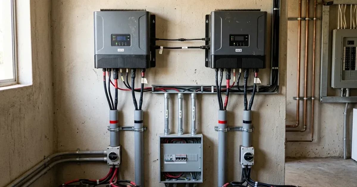
- CAN Connection: CAN lines are daisy-chained between inverters. This means the communication cable runs from one inverter to the next in a series.
- AC Wiring (Backup Load & Home Load): All inverters' L, N, and PE lines must be connected to a common busbar.
- AC Wiring (Grid): Similarly, all inverters' L, N, and PE lines are connected to a common busbar for the grid connection.
- CT Connection (Single Phase): The Current Transformer (CT) is connected to the main grid line. Its second side must be connected only to the master inverter.
- CT Connection (Three Phase): For three-phase systems, three CTs are used on the grid lines, with arrows pointing towards the inverter.
LCD Parallel Settings
On the inverter's LCD, you must configure the following:
- Parallel: Enable this function when several Deye hybrid inverters of the same model are connected in parallel.
- Master: Select one hybrid inverter in the parallel system to act as the master. This inverter manages the working mode of the entire parallel system.
- Slave: Set all other inverters managed by the master inverter as slave inverters.
- Modbus SN: The Modbus address of each inverter must be different.
- A/B/C Phase: When forming a three-phase system in parallel, you must set which phase (A, B, or C) each inverter belongs to.
For more general information on inverter fault codes, you can refer to our guide on solar inverter fault codes explained. If the issue involves battery communication, our article on troubleshooting battery communication errors in solar inverters may be helpful.
Safety: Working with Parallel Inverter Systems
Working with multiple inverters connected in parallel involves significant electrical hazards. Always prioritize safety.
- Electrical Shock Risk: To reduce the risk of electric shock, disconnect all AC and DC wires from all inverters and wait for capacitors to discharge before attempting any maintenance or cleaning. Turning off the unit alone does not eliminate this risk.
- Battery Handling: Be very cautious when working with metal tools on or around batteries. Dropping a tool may cause a spark or short circuit in batteries or other electrical parts, potentially causing an explosion.
- Wiring Disconnection: Strictly follow the installation procedure when disconnecting AC or DC terminals. Ensure all power sources are isolated.
- Grounding: The inverter should be connected to a permanent grounded wiring system, complying with local requirements. The ground cable must be connected to the ground plate on the grid side to prevent electric shock.
- Professional Installation: All wiring must be performed by a professional person. Incorrect wiring can lead to severe damage or injury.
- Polarity: Before making the final DC connection, ensure positive (+) is connected to positive (+) and negative (-) to negative (-). Reverse polarity connection on the battery will damage the inverter.
When to call a technician instead
If you have followed all troubleshooting steps, verified all connections, and confirmed all settings, but the Deye parallel operation errors (F29, F41, or others) persist, it is time to contact a qualified solar technician or your local Deye service center. Provide them with the inverter serial number, the date of grid connection, a detailed description of the problem (including fault codes and indicator status), and your contact information. Attempting repairs beyond basic checks can void your warranty or lead to further damage.
Still showing the fault? Book a technician
If the steps above did not clear it, tell us the inverter or battery and the exact code. We pass it to a technician who covers your city; visit charges are quoted before they come.
How this pays for the site: the technician or verifier pays SolarNevs a fixed introduction fee. Nobody pays to be recommended, and you are free to use our free guides instead.
Frequently asked questions
What does Deye F29 Parallel CANBus fault mean?
The Deye F29 error indicates a problem with the parallel communication cable connection or the communication address settings between inverters. This fault can also appear temporarily during system startup.
What causes a Deye F41 Parallel system stop error?
The Deye F41 error typically occurs when one of the hybrid inverters in a parallel system is in an OFF status. All inverters in the parallel system must be operational.
How do I set up Deye inverters for parallel operation?
For parallel operation, you must enable the 'Parallel' function on the LCD, designate one inverter as 'Master' and others as 'Slave', and ensure each inverter has a different 'Modbus SN'. Physical CAN lines must be daisy-chained, and DIP switches 1&2 set to ON for up to six inverters.
How many Deye inverters can be connected in parallel?
Deye inverters support parallel operation. For systems with six or fewer inverters, all DIP switches 1&2 should be ON. If more than six inverters are used, only the main six should have DIP switches 1&2 ON, with others OFF.
What are the safety precautions when troubleshooting Deye parallel errors?
Always disconnect all AC and DC power sources to all inverters and wait for capacitors to discharge before inspecting or modifying any wiring. Be cautious with metal tools around batteries to prevent short circuits and potential explosions. Attempting repairs beyond basic checks can void your warranty or lead to further damage; contact a qualified technician if unsure.
References
- Deye SUN-3.6-6K-SG03LP1-EU Inverter Manual Ver2.2 — accessed 23 August 2026
- Deye SUN-7.6-8K-SG01LP1-EU Inverter Manual — accessed 23 August 2026
- Deye SUN-3-6K-SG04LP1-EU-SM2 Inverter Manual — accessed 23 August 2026
Related guides
More from inverter errors & fixes.