Maxpower Lithium Battery: SOC Readings and Alarm Light Meanings
Updated 6 September 2026 · By SolarNevs Research Desk, Dealer surveys + verified sources · 5 sources · Method ↗
Key Takeaways
- Maxpower publishes no official battery fault-code manual or LED table; diagnostics rely on front-panel LED indicators (following Pylontech rack conventions), Bluetooth telemetry on Alpha models, and connected inverter fault screens.
- Following regional LiFePO4 rack conventions, a flashing red ALM light signals an approaching parameter warning, while a solid red ALM light indicates an active BMS protection lockout where power transfer is refused (never bypass protection lockouts by hard-cycling the pack).
- Beware of the MP-5000 model variant trap: the MP-5000 Alpha is a 51.2 V / 100Ah pack (with a 40–58.4 V operating range, where ambient heat derates charging within the published 0°C–55°C window), while the MP-5000 PRO is an electrically distinct 24V pack (25.6 V / 200Ah, operating with published setpoints of 28.8 V bulk, 27.6 V float, and 25.6 V low cutoff; noting that ambient heat derates charging within the published 0°C–55°C operating window).
- Inverter SOC discrepancies (where inverter-side SOC can read 20–40% off battery SOC) occur when digital BMS communication is absent; restore closed-loop CAN/RS485 links or execute a full 100% calibration cycle.
Quick Answer: How to interpret Maxpower lithium SOC and alarm lights
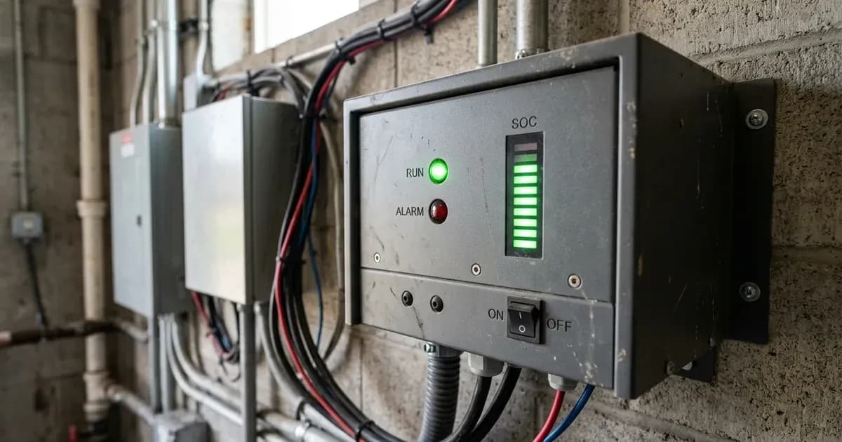
To diagnose a Maxpower MP-series battery (such as MP-5000 Alpha, MP-5000 PRO, or MP-10000 PRO), examine the front-panel LED bar. Under standard LiFePO4 rack conventions (Pylontech Powercube analogue), a solid green RUN light indicates active charging (flashing during discharge or idle), while the green SOC LED ladder displays remaining capacity.
A flashing red ALM lamp warns of approaching thermal or voltage limits, whereas a solid red ALM lamp indicates that the internal BMS contactor has tripped to protect the pack (due to voltage outside the published 40–58.4 V range on Alpha models where ambient heat derates charging within the published 0°C–55°C charge window, low DC cutoff, or temperature faults outside the 0°C–55°C charge / −30–60°C discharge windows). On Alpha models, connect via the Bluetooth mobile app to inspect individual cell voltages directly.
To check pricing and model specs across the lineup, see our comprehensive guide on Maxpower lithium battery prices in Pakistan.
Official Documentation Baseline and Sourcing Context
Maxpower (a brand of Maxell Power Pvt Ltd, Lahore) catalogues a lithium-only MP-series battery line spanning 14 SKUs from 1.2 kWh to 32 kWh. While product pages publish key electrical limits (such as the 40–58.4 V range for the MP-5000 Alpha and 28.8 V bulk / 27.6 V float / 25.6 V low cutoff for the 24V MP-5000 PRO, noting that ambient heat derates charging within the published 0°C–55°C operating window), the manufacturer publishes no standalone user manual, LED truth table, or numerical battery fault-code list.
Diagnostic decoding in this guide rests on verified manufacturer product specifications, Max Power technical engineering articles, and established regional 48V LiFePO4 rack conventions (Pylontech Powercube analogue).
Master LED Status and Inverter Alarm Reference Table
Indicator / Symptom | LED Pattern / Inverter Code | Operational Meaning | Recommended Action |
|---|---|---|---|
Normal Operation (Charging) | RUN Green Solid + SOC LEDs climbing | Battery actively accepting charge current | Normal operation; verify charging current matches module spec (50A on MP-5000 Alpha / 100A std on MP-10000 PRO) |
Normal Operation (Discharging) | RUN Green Flashing + SOC LEDs solid | Battery supplying load current | Normal operation; monitor discharge depth against 80% DoD target (delivering 8 kWh on MP-10000 Alpha) |
Standby / Idle State | RUN Green Slow Flash | Pack energized with zero current draw | Normal idle state; not a fault condition |
BMS Warning Alert | ALM Red Flashing | Parameter approaching operational limit | Check ambient temperature and charging voltage ceiling |
BMS Protection Lockout | ALM Red Solid | BMS disconnected charge/discharge contactor | Isolate DC breaker using insulated tools, check cell voltages via Bluetooth, allow cooldown; never hard-cycle to clear |
Inverter Comms Fault | Growatt Warning 20 / Solis CAN_Comm-Fail | Digital CAN/RS485 handshake broken | Inspect RJ45 cable pins (pin 4 CAN-H, pin 5 CAN-L) and port seating |
Inverter Over-Temp / Over-Charge | Max Power Hybrid F02 / F03 | Inverter-side thermal or charging fault | Ensure inverter ventilation; verify bulk charge ceiling |
Figures as of August 2026.
Step-by-Step Diagnostic and SOC Decoding Rules
1. Front-Panel LED Decoding (Industry Convention)
Because Maxpower publishes no proprietary LED manual, field technicians decode indicators using established 48V LiFePO4 rack architecture (Pylontech Powercube analogue):
- RUN Indicator: Solid green indicates active absorption or bulk charging. Flashing green indicates current discharging to load. A slow pulse with SOC LEDs extinguished indicates standby idle.
- ALM Indicator: A flashing red light warns of high temperature or cell delta voltage before a lockout occurs. A steady, solid red light indicates that the BMS has opened its protection MOSFETs or DC contactor refusing charge/discharge for cause (never bypass protection lockouts by hard-cycling the pack).
- SOC Indicator Bar: The LED bar provides an approximate visual State of Charge. Each illuminated green LED represents a proportional segment of the battery's total usable energy.
2. Identifying Model Electrical Variants (The MP-5000 Distinction)
Troubleshooting battery voltage readings requires verifying your exact model SKU, as Maxpower uses similar model numbers for electrically distinct architectures:
- MP-5000 Alpha: 51.2 V nominal, 100Ah capacity (5.12 kWh), with an operating voltage range of 40–58.4 V (derived 16S LiFePO4 arithmetic at 2.5–3.65 V/cell, noting that ambient heat derates charging within the published 0°C–55°C window), 50A charge / 100A discharge ratings, and integrated Bluetooth monitoring.
- MP-5000 PRO: 25.6 V nominal (24V class!), 200Ah capacity (5.12 kWh), with factory charging parameters of 28.8 V bulk, 27.6 V float, and 25.6 V low DC cutoff (where high ambient heat derates charging within its published 0°C–55°C operating window), 100A std / 200A max charge current, featuring CAN and RS485 ports.
- MP-10000 PRO: 51.2 V nominal (operating within the published 0°C–55°C charge temperature window), 200Ah capacity (10.24 kWh), floor-standing unit with 100A standard / 200A maximum charge current, 10.24 kW discharge, 15 parallel support, and dual CAN/RS485 communication.
3. Understanding Inverter SOC Jumping and Calibration Drift
When solar inverters are connected to lithium batteries without active CAN or RS485 communication, they calculate SOC using battery voltage. Because LiFePO4 cells maintain an exceptionally flat discharge voltage plateau, minor load changes cause estimated percentages to jump (inverter-side SOC can read 20–40% off battery SOC).
- Closed-Loop Remediation: Connect the RJ45 communication lead between the battery CAN port (pin 4 CAN-H, pin 5 CAN-L) and the inverter BMS port to transmit true Coulomb-counted SOC telemetry. Disconnect DC power and use insulated tools during connection to avoid short circuits.
- Manual Calibration Cycle: If running in open-loop voltage mode, charge the pack continuously until cell voltages reach full absorption (56.8–57.6 V boost/absorb on 51.2 V class models, derived community practice; doubling the 24V PRO set yields 57.6 V bulk / 55.2 V float / 51.2 V cutoff; noting that ambient heat derates charging within the published 0°C–55°C operating window), allowing the internal BMS to calibrate its 100% SOC reference.
4. Overcast Monsoon Recovery via Hybrid Priority Mode
During prolonged monsoon cloud cover, lithium packs may fail to reach 100% SOC from solar alone. Without periodic full charges, open-loop SOC estimates drift out of calibration (community-reported). Max Power's engineering articles recommend enabling Hybrid Priority Mode on its hybrid inverters to blend solar generation with off-peak utility grid power so the battery completes a periodic full saturation charge.
For wiring and communication cable repairs, see our guide on Maxpower lithium BMS fault and comms fixes and configure inverter parameters in Maxpower lithium inverter pairing settings. Understand internal BMS hardware protection in our guide on BMS functions and battery protection.
Safety: LiFePO4 Protection and Handling Guidelines
Observe these mandatory safety rules when troubleshooting Maxpower lithium batteries:
- Never Bypass Protection Trips: If the red ALM LED is solid, do not attempt to bypass the BMS by connecting external raw chargers or hard-cycling the pack. The BMS trips to prevent cell damage from voltage outside the 40–58.4 V operating range (where ambient heat derates charging within the 0°C–55°C window), short circuits, or thermal extremes outside the 0°C–55°C charge / −30–60°C discharge limits.
- Temperature Operating Bounds: Charging is permitted only between 0°C and 55°C; discharging operates from −30°C to 60°C (per PRO specifications). In Pakistani summer conditions, maintain ventilated indoor installation as the 55°C top end derates charging.
- DC Isolation and Terminal Servicing: Always disconnect DC power and isolate inverter circuits before handling wiring. Use insulated tools when working near terminals, because an uninsulated spanner dropped across battery terminals shorts hundreds of amperes.
- Enclosure Security: Maxpower packs carry an IP20 indoor rating and contain no user-serviceable internal components. Never break factory seals or open the metal casing, as the cell maker and assembly location remain undisclosed.
When to call a technician instead
Contact an authorized Maxpower dealer (Maxell Power Pvt Ltd, Lahore) or qualified solar technician under the following circumstances:
- The red ALM protection light remains solid red after disconnecting loads and power cycling the DC isolator using insulated tools.
- Pack terminal voltage sits below the operating floor of the MP-5000 Alpha's published 40–58.4 V range (where ambient heat derates charging within the published 0°C–55°C window).
- The Bluetooth monitoring application reports persistent cell voltage imbalance or hardware protection events.
- The battery pack fails to communicate with the solar inverter despite verifying RJ45 pinout wiring (pin 4 CAN-H, pin 5 CAN-L).
For professional escalation standards, consult our guide on when to call a solar technician.
Figures as of August 2026.
Still showing the fault? Book a technician
If the steps above did not clear it, tell us the inverter or battery and the exact code. We pass it to a technician who covers your city; visit charges are quoted before they come.
How this pays for the site: the technician or verifier pays SolarNevs a fixed introduction fee. Nobody pays to be recommended, and you are free to use our free guides instead.
Frequently asked questions
What does a solid red ALM light mean on a Maxpower lithium battery?
Following regional LiFePO4 rack conventions (Pylontech Powercube analogue), a solid red ALM light indicates a BMS protection lockout (such as voltage outside the published 40–58.4 V operating range on MP-5000 Alpha where ambient heat derates charging within the published 0°C–55°C window, over-current, or temperatures outside 0°C–55°C charge / −30–60°C discharge). In this state, the internal contactor opens and charging/discharging is refused for cause; never bypass protection lockouts by repeatedly hard-cycling the pack.
What is the difference between a flashing and solid red ALM LED?
Under standard rack LED conventions (Pylontech Powercube analogue), a flashing red ALM light indicates an operational warning or approaching operating limit while the pack continues to run. A solid red ALM indicator signifies a full hardware fault or BMS protection lockout that halts power transfer.
Why is the inverter SOC percentage jumping or not matching the battery?
If closed-loop CAN or RS485 communication is disconnected, the inverter estimates SOC solely from battery terminal voltage. Because LiFePO4 chemistry has a flat voltage curve, open-loop voltage estimation causes rapid percentage jumps (inverter-side SOC can read 20–40% off battery SOC) until a complete 100% charge-and-discharge calibration cycle is performed.
What operating voltage window does Maxpower specify for the MP-5000 Alpha?
Maxpower's official product specifications define an operating range of 40–58.4 V for the 51.2 V 100Ah MP-5000 Alpha (derived arithmetic: 16S LiFePO4 at 2.5–3.65 V/cell, noting that ambient heat derates charging within the published 0°C–55°C window). By contrast, the 24V class MP-5000 PRO (25.6 V / 200Ah) operates with published setpoints of 28.8 V bulk, 27.6 V float, and 25.6 V low DC cutoff (noting that high ambient heat derates charging within its published 0°C–55°C operating window).
Does Maxpower publish an official error code manual for its lithium batteries?
No. Maxpower (Maxell Power Pvt Ltd) publishes no standalone battery error-code manual, LED truth table, or numerical fault list. Battery diagnostics are read via front-panel LED indicators (Pylontech rack analogue), Bluetooth monitoring on Alpha models, or fault codes (such as F02 over-temperature and F03 overcharge) displayed on connected Max Power hybrid inverters.
References
- Max Power MP-5000 Alpha Product Specifications — accessed 23 August 2026
- Max Power MP-5000 PRO Product Specifications — accessed 23 August 2026
- Max Power Hybrid Inverter Problems Article — accessed 23 August 2026
- Max Power Best Lithium-Ion Batteries in Pakistan Article — accessed 23 August 2026
- Pylontech Powercube Manual via ManualsLib — accessed 23 August 2026
Related guides
More from inverter errors & fixes.