Osaka Battery with Solar Inverter: Essential Settings for Pairing
Updated 7 September 2026 · By SolarNevs Research Desk, Dealer surveys + verified sources · 4 sources · Method ↗
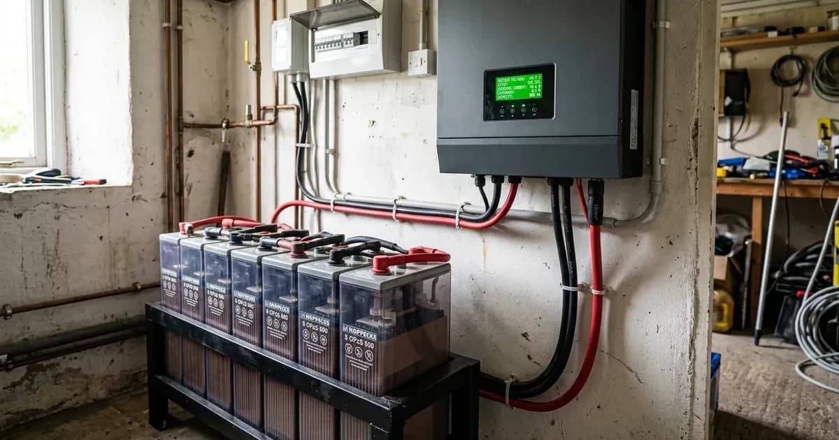
Key Takeaways
- Select the Flooded battery type preset (Program 05) on your inverter to avoid chronic undercharging from AGM defaults.
- Configure 48V bulk absorption voltage to 57.6 V–58.8 V (14.4 V–14.7 V per 12V battery block) and float voltage to the inverter default of 54.0 V (referenced to 25°C; apply −3 to −5 mV/cell/°C temperature compensation above 25°C in hot installations).
- Continuous floating at Osaka's upper 55.2 V–56.8 V standby band accelerates water loss and electrolyte boiling in ambient heat above 35°C; keep float at 54.0 V (referenced to 25°C; apply −3 to −5 mV/cell/°C temperature compensation above 25°C in hot installations) and use periodic equalization to de-stratify acid (which drives cells into the hydrogen gassing region and requires a ventilated space away from sparks and flames).
- Osaka publishes no proprietary equalization schedule or low DC cutoff; use Axpert engineering defaults (58.4 V equalization referenced to 25°C with −3 to −5 mV/cell/°C temperature compensation above 25°C in hot installations for 60 minutes every 30 days in a ventilated space away from sparks and flames; 42.0 V low cutoff with an adjustable range of 42.0 V–48.0 V).
- Osaka tubular batteries feature no BMS or communication protocols; pairing is performed entirely through manual inverter voltage programming.
Quick Answer: How to configure your inverter for Osaka tubular batteries
To correctly pair Osaka flooded tubular batteries (such as the TA-1800, TA-2500, TA-3000, or current HT-series badges like HT-1800, HT-2000, HT-2500, and HT-3500) with a solar inverter, configure Program 05 to Flooded (or User-Defined if fine-tuning parameters). Set bulk charging to 57.6 V–58.8 V (14.4 V–14.7 V per 12V block) at 25°C reference (apply −3 to −5 mV/cell/°C temperature compensation in ambient heat).
Because Osaka publishes no official equalization frequency or low-voltage cutoff threshold in its technical documentation, installers rely on verified inverter defaults: maintain float at 54.0 V (at 25°C reference; apply −3 to −5 mV/cell/°C temperature compensation in ambient heat), schedule automated 30-day equalization at 58.4 V for 60 minutes (referenced to 25°C with −3 to −5 mV/cell/°C temperature compensation in ambient heat; equalization deliberately drives cells into the hydrogen gassing region, so maintain active ventilation away from sparks and flames), and set low DC cutoff no lower than the default 42.0 V (adjustable range 42.0 V–48.0 V).
If you are weighing replacement cost or comparing alternatives, consult our separate analysis of Osaka battery prices in Pakistan.
Master Inverter Settings and Parameters Table for Osaka Tubular Batteries
The table below compiles verified parameter targets across the Osaka Tubular Technical Data Sheet and major off-grid inverter platforms (Voltronic Axpert and Growatt SPF 5000 ES series):
Parameter / Setting Name | Osaka Datasheet Specification | Axpert VM III Setting (48V) | Axpert V PF1 Setting (48V) | Growatt SPF 5000 ES Setting |
|---|---|---|---|---|
Battery Type | Flooded Tubular (OPzS 12V) | Program 05: Flooded (or User-Defined) | Program 05: Flooded (or User) | Program 05: FLD (or USE) |
Bulk / Absorption Voltage | 14.4 V–14.7 V (57.6 V–58.8 V on 48V) | Program 26: 58.4 V (default) | Program 26: 56.4 V (raise in USE) | Program 19: 58.4 V (range 48.0 V–58.4 V) |
Float / Standby Voltage | 13.8 V–14.2 V (55.2 V–56.8 V on 48V) | Program 27: 54.0 V (default) | Program 27: 54.0 V (default) | Program 20: 54.0 V (range 48.0 V–58.4 V) |
Equalization Voltage | 14.1 V–14.4 V (boost charge) | Program 31: 58.4 V (Program 30 enable) | Program 31: 58.4 V | Supported for flooded (see manual) |
Equalization Interval | Not published by Osaka | 35: every 30 days (range 0–90 days) | 30-day interval | Check manual |
Equalization Duration | Not published by Osaka | 33: 60 min | 60 min | Check manual |
Low DC Cutoff Voltage | Not published by Osaka | Program 29: 42.0 V (range 42.0 V–48.0 V) | Program 29: 42.0 V (range 42.0 V–48.0 V) | Check manual (verify on unit) |
Max Charge Current Ceiling | 0.1 × C10 (16 A boost on TA-2500) | Program 02: 20 A–30 A (up to 80 A) | Program 02: 20 A–30 A (10-120A options) | Program 02: 20 A–30 A (per program 11/02) |
Figures as of August 2026.
Detailed Setting Explanations and Practical Rules
1. Battery Type Selection (Program 05)
On Voltronic Axpert-family inverters — including Inverex, Knox, Fronus, and Crown rebadges — Program 05 defaults to AGM. On Growatt SPF units, check Program 05 and select FLD. The AGM preset caps bulk charging at 56.4 V, which leaves flooded tubular batteries chronically undercharged compared to the 58.4 V flooded target (setpoints referenced to 25°C; apply −3 to −5 mV/cell/°C temperature compensation above 25°C in hot installations). Selecting Flooded raises the bulk charge target to 58.4 V on Axpert VM III and makes the periodic equalization routine available (enable it via Program 30), which drives cells into the hydrogen gassing region, requiring active ventilation away from sparks and flames.
2. Bulk and Absorption Voltage Configuration
Osaka's datasheet specifies a cycle use voltage range of 14.4 V to 14.7 V per 12V battery (57.6 V to 58.8 V across a 48V series bank) referenced to 25°C. In high ambient heat above 25°C, apply −3 to −5 mV/cell/°C temperature compensation (for example, on a 48V bank at 45°C, 57.6 V reduces to ~55.7 V). While the Axpert VM III Flooded preset defaults to 58.4 V (placing it squarely within Osaka's 57.6 V–58.8 V band), the older Axpert V PF1 defaults to 56.4 V. Owners of Axpert V PF1 units should switch Program 05 to User-Defined (USE) and manually configure Program 26 at 58.4 V (within user range 48.0 V–61.0 V) to prevent plate sulfation.
3. Float Voltage Reconciliation: Inverter Default vs Datasheet
Osaka's technical datasheet lists standby float voltage between 13.8 V and 14.2 V (55.2 V to 56.8 V for a 48V bank) at 25°C reference. However, continuous floating at 55.2 V–56.8 V in ambient heat above 35°C accelerates water loss and boils electrolyte. Technicians advise retaining the inverter standard 54.0 V float default (Program 27 on Axpert VM III and Axpert V PF1; Program 20 on Growatt SPF 5000 ES; referenced to 25°C with −3 to −5 mV/cell/°C temperature compensation above 25°C in hot installations), allowing the monthly equalization charge (enabled via Program 30) to de-stratify acid. Because equalization deliberately drives cells into the hydrogen gassing region, ensure the battery room is well-ventilated away from sparks and flames.
4. Low DC Cutoff and Deep Discharge Discipline
Osaka's technical discharge chart places fully discharged capacity at 11.80 V per 12V block. Inverter defaults (Axpert Program 29) set low DC cutoff at 42.0 V with an adjustable range of 42.0 V–48.0 V. Leaving the cutoff at 42.0 V allows the bank to drain well below Osaka's discharged mark under heavy loads. Technicians advise setting cutoff no lower than the default (42.0 V), and strongly recommend raising Program 29 toward the upper end of the 42.0 V–48.0 V range in User-Defined mode to protect positive tubular plates from routine deep discharge.
5. Charge Current Sizing (Program 02)
Osaka recommends continuous charging currents of approximately 0.1 × C10 capacity (12–13h) and boost currents of 0.1–0.2 × C10 (conducted in a ventilated space away from sparks and flames, as boost charging drives cells into the hydrogen gassing region). For a TA-2500 battery (250Ah @20HR official / roughly 230Ah @10HR, weight 63.5 kg), the initial boost charge is rated at 16 A per block. Because series strings share the same current, set inverter Program 02 to a conservative ceiling of 20 A to 30 A for a single 48V string.
Learn how to troubleshoot uncharged banks in our guide on Osaka battery not charging and low backup fixes and maintain electrolyte in our Osaka battery care, water, and gravity guide.
6. Equalization Boost Setting vs Inverter Defaults
For boost and equalization charging, Osaka's datasheet specifies 14.1 V to 14.4 V per 12V block (56.4 V to 57.6 V on 48V) to reverse sulfation, whereas Axpert inverters apply 58.4 V in Program 31 for 60 minutes every 30 days (setting 33 for 60 min duration and setting 35 for 30-day interval; all setpoints referenced to 25°C, with −3 to −5 mV/cell/°C temperature compensation above 25°C in hot installations). Because equalization deliberately drives the cell into the hydrogen gassing region (~2.4V/cell and above), always conduct equalization in an actively ventilated area away from sparks and open flames.
Clone Inverters and Menu Navigation in Pakistan
Many popular solar inverters sold in Pakistan (including Knox, Fronus, Crown, and Inverex models) are built on Voltronic power boards. Consult our investigative guide on Chinese vs local brand inverters and rebadging to identify your underlying hardware platform.
When navigating inverter menus on rebadged units, match settings by descriptive parameter name rather than relying solely on menu program numbers, as firmware revisions occasionally alter menu indexes.
Verification Steps After Programming
Once you have entered the charging voltage and current parameters into your solar inverter, perform the following operational checks:
- Monitor Bulk Charge Transition: During peak solar production hours, verify on the inverter LCD that battery voltage climbs steadily toward 57.6 V–58.4 V without triggering over-voltage warnings (all setpoints referenced to 25°C; apply −3 to −5 mV/cell/°C temperature compensation above 25°C in hot ambient conditions).
- Verify Float Voltage Drop: After absorption charging completes, confirm that charging voltage drops back to 54.0 V (referenced to 25°C; apply −3 to −5 mV/cell/°C temperature compensation above 25°C in hot ambient conditions) on the inverter display.
- Check Electrolyte Activity: Inspect cell vent caps; normal charging produces slight effervescence, whereas violent bubbling accompanied by casing heat exceeding 50°C indicates excessive charging voltage or overcharge. If the battery becomes hot to touch (50°C+), take it off charge immediately.
- Hydrometer Discipline: When verifying specific gravity across cells (full charge reads 1.260 at 25°C; 27°C reference requires temperature correction of ~4 points per 6°C), always wear eye protection and gloves, because hydrometer testing draws sulfuric acid out of the cell.
Safety: Inverter Programming Precautions
Observe these mandatory safety precautions when modifying inverter battery settings and handling flooded tubular banks:
- Capacitor Discharge Wait: Turn off the inverter AC switch and disconnect DC isolators. Wait at least 5 minutes for internal high-voltage DC bus capacitors to discharge before touching terminal connections.
- Insulated Tooling and Terminal Safety: Always kill power and open DC disconnect breakers before tightening terminal bolt-nut connections using insulated tools, because a spanner across a battery bank shorts hundreds of amps. (Osaka publishes no torque figure; terminals are bolt-nut).
- Ventilation During Equalization: Ensure battery storage rooms have active ventilation during 58.4 V equalization charging (referenced to 25°C with −3 to −5 mV/cell/°C temperature compensation above 25°C in hot installations) to prevent explosive hydrogen gas accumulation, as equalization deliberately drives cells into the gassing region (~2.4V/cell and above).
- Electrolyte Handling: Always wear eye protection and chemical-resistant gloves when checking specific gravity or adding water; add distilled or demineralized water only, never acid.
- Heavy Lifting: Osaka tall tubular batteries present serious handling hazards: TA-1800 (~54.9 kg), TA-2500 (63.5 kg), and TA-3000 (72.7 kg) require a two-person lift.
When to call a technician instead
Contact a certified solar professional under the following conditions:
- The inverter repeatedly faults with over-voltage or under-voltage alarms despite verifying battery type (Program 05), bulk charging (Program 26), and float charging settings.
- Electrolyte boils vigorously and overheats during normal 54.0 V float charging (referenced to 25°C; apply −3 to −5 mV/cell/°C temperature compensation above 25°C in hot installations).
- Battery casing exhibits structural swelling or acid leakage.
For professional escalation standards, consult our guide on when to call a solar technician.
Figures as of August 2026.
Still showing the fault? Book a technician
If the steps above did not clear it, tell us the inverter or battery and the exact code. We pass it to a technician who covers your city; visit charges are quoted before they come.
How this pays for the site: the technician or verifier pays SolarNevs a fixed introduction fee. Nobody pays to be recommended, and you are free to use our free guides instead.
Frequently asked questions
What battery type setting should I select for Osaka tubular batteries?
Select the 'Flooded' battery type (Program 05 on Axpert and Growatt inverters). This engages the multi-stage flooded lead-acid charging profile rather than the lower-voltage sealed AGM profile (the factory default on Axpert-family units).
What are the recommended bulk and float voltages for Osaka tubular batteries?
Osaka's datasheet specifies 14.4 V–14.7 V for cycle bulk/absorption (57.6 V–58.8 V on a 48V bank) and 13.8 V–14.2 V standby (55.2 V–56.8 V on 48V). These setpoints are referenced to 25°C; in ambient heat above 25°C, apply −3 to −5 mV/cell/°C temperature compensation. Because continuous 55.2 V–56.8 V floating sits above the inverter 54.0 V default and risks boiling electrolyte in ambient heat above 35°C, installers advise following the inverter 54.0 V default float and relying on periodic equalization to de-stratify acid. Because equalization deliberately drives cells into the hydrogen gassing region, perform it only in a well-ventilated space away from sparks and open flames.
Do Osaka tubular batteries require equalization charging?
Yes. Osaka publishes no equalization schedule of its own, so installers follow inverter defaults: on Axpert platforms, enable equalization (Program 30, available under Flooded or User-Defined profiles) and the defaults apply 58.4 V for 60 minutes every 30 days (referenced to 25°C; apply −3 to −5 mV/cell/°C temperature compensation in ambient heat). Because equalization deliberately drives the cell into the hydrogen gassing region, perform it only in a well-ventilated space away from sparks and open flames.
What is the maximum charge current for Osaka tubular batteries?
Osaka recommends an initial charging current of approximately 0.1 times C10 capacity (0.1×C10 to 0.2×C10 for boost). For a TA-2500 battery (250Ah @20HR official, roughly 230Ah @10HR), Osaka's datasheet specifies an initial boost current of 16 A per 12V block. For a 48V series string, installers set Program 02 to a conservative ceiling of 20 A–30 A.
Do Osaka tubular batteries communicate with inverters via digital cables?
No. Osaka tubular batteries are flooded lead-acid units with no BMS, no CAN/RS485 comms ports, and no protocol pairing. They pair with solar inverters entirely through manual voltage settings.
References
- Osaka Tubular Technical Data Sheet PDF — accessed 23 August 2026
- Axpert VM III User Manual — accessed 23 August 2026
- Axpert V PF1 User Manual — accessed 23 August 2026
- Growatt SPF 5000 ES User Manual — accessed 23 August 2026
Related guides
More from inverter errors & fixes.