SolarMax Inverter Battery Not Charging: Troubleshooting Guide
Updated 7 September 2026 · By SolarNevs Research Desk, Dealer surveys + verified sources · 1 source · Method ↗
Key Takeaways
- The most likely causes for a SolarMax inverter not charging its battery are critically low battery voltage, incorrect inverter settings, or a disconnected battery.
- Your first step should be to check the inverter's LCD display for any fault codes and measure the battery voltage directly.
- Always disconnect all power sources (PV, AC, battery) before inspecting or tightening battery terminals.
- Stop DIY troubleshooting and contact a qualified technician if internal component failures are indicated by fault codes or if the problem persists after checking basic connections and settings.
Why is my SolarMax inverter not charging its battery?
If your SolarMax inverter is not charging its battery, the most common causes include critically low battery voltage, incorrect charging settings on the inverter, or a physical disconnection of the battery. The first step is to check the inverter's display for any fault codes and verify the battery's voltage.
Diagnosis
Follow these steps to diagnose why your SolarMax inverter is not charging its battery. Remember that menu/program numbering can differ by model and firmware on rebadged units; you must match settings by NAME rather than by number.
- Check the Inverter Display for Fault Codes:
- Look for any fault codes or warning indicators on the LCD screen.
- Fault Code 04 (Battery voltage is too low): This indicates the battery voltage is below the operational threshold.
- Fault Code 03 (Battery voltage is too high): This suggests an overcharge condition or an issue with battery specifications.
- Warning Indicator (No Code) - Battery is not connected: This means the inverter does not detect a battery.
- If you see other fault codes, refer to the "Fault Codes" table below for their meanings.
- Measure Battery Voltage:
- Safely disconnect all power sources (PV, AC, battery) from the inverter.
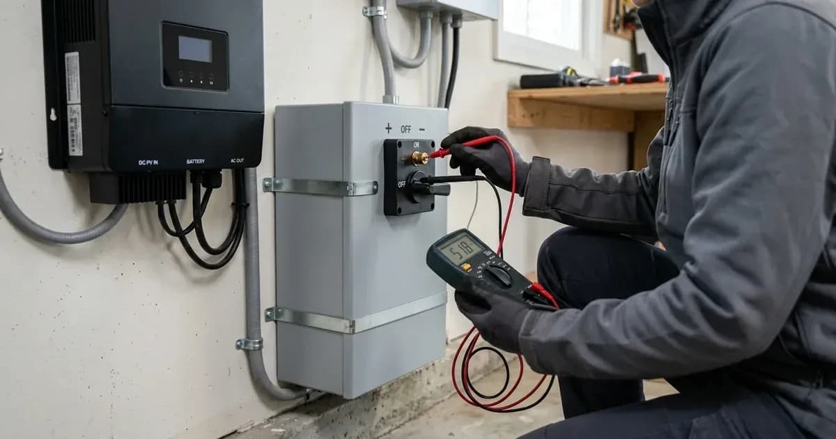
- Using a multimeter, measure the voltage directly across your battery terminals.
- If the battery voltage is too low (e.g., below 1.91V/Cell for startup, or below 1.4V/Cell for no response), the inverter may not be able to initiate charging.
- Safety Warning: Be very cautious when working with metal tools on or around batteries to avoid sparks, short circuits, or explosions. Always use insulated tools.
- Inspect Battery Connections:
- With all power disconnected, visually inspect the battery cables for any loose, corroded, or damaged connections at both the battery and inverter terminals.
- Tighten any loose connections. A loose connection can prevent proper charging.
- Safety Warning: Disconnect all wirings before maintenance or cleaning to reduce electric shock risk. Turning off the unit does not reduce this risk. Strictly follow installation procedure when disconnecting AC or DC terminals.
- Verify Inverter Settings:
- Access the inverter's LCD settings menu.
- Program 05 (Battery type): Select the type of deep-cycle lead-acid battery you have installed. Options include 'AGM (default)', 'Flooded', and 'User-Defined'. For optimal charging and battery longevity, select the type that matches your lead-acid battery. The inverter is designed to charge only deep-cycle lead-acid batteries; other types may burst. Menu/program numbering can differ by model and firmware on rebadged units. You must match settings by NAME rather than by number.
- Program 02 (Maximum charging current): Check if the maximum charging current is set appropriately for your battery bank's capacity. A setting that is too low will result in slow or insufficient charging. Menu/program numbering can differ by model and firmware on rebadged units. You must match settings by NAME rather than by number.
- Program 11 (Maximum utility charging current): If charging from the grid, ensure this current is also set correctly. Menu/program numbering can differ by model and firmware on rebadged units. You must match settings by NAME rather than by number.
- Program 16 (Charger source priority): This determines which source the inverter prioritizes for charging. Menu/program numbering can differ by model and firmware on rebadged units. You must match settings by NAME rather than by number.
- "Solar first": Prioritizes solar charging.
- "Solar and Utility (default)": Uses both solar and utility to charge.
- "Only Solar": Charges only from solar.
- Program 26 (Bulk Charging Voltage) and Program 27 (Floating Charging Voltage): If using "User-Defined" battery type, ensure these voltages match your battery manufacturer's specifications. Incorrect voltages can prevent charging or damage the battery. Menu/program numbering can differ by model and firmware on rebadged units. You must match settings by NAME rather than by number.
- Program 29 (Low DC cut-off voltage): While not directly a charging setting, an extremely low cut-off voltage can allow the battery to discharge too deeply, making it harder for the inverter to initiate a charge cycle. Menu/program numbering can differ by model and firmware on rebadged units. You must match settings by NAME rather than by number.
Cause/fix table section
Symptom detail | Likely cause | Fix |
|---|---|---|
Inverter display shows Fault Code 04 | Battery voltage is too low | Re-charge battery. Replace battery. |
Inverter display shows Fault Code 03 | Battery voltage is too high | Check if spec and quantity of batteries are meet requirements. |
Inverter display shows "Battery is not connected" (No Code) | Battery is not connected | Check battery connections at both the inverter and battery terminals. |
Unit shuts down automatically during startup process. | The battery voltage is too low (<1.91V/Cell) | Re-charge battery. Replace battery. |
No response after power on. No indication. | The battery voltage is far too low. (<1.4V/Cell) | Re-charge battery. Replace battery. |
Inverter not charging from solar panels | Charger source priority (Program 16) set to "Utility first" or "Solar and Utility (default)" with insufficient solar input. | Set Program 16 to "Solar first" or "Solar and Utility (default)" and ensure adequate PV input. Menu/program numbering can differ by model and firmware on rebadged units. You must match settings by NAME rather than by number. |
Inverter not charging from utility (grid) | Charger source priority (Program 16) set to "Solar first" or "Only Solar". | Set Program 16 to "Solar and Utility (default)". Menu/program numbering can differ by model and firmware on rebadged units. You must match settings by NAME rather than by number. |
Slow or insufficient charging | Maximum charging current (Program 02) or Maximum utility charging current (Program 11) set too low for battery capacity. | Increase current in Program 02 and/or Program 11. For 1.5KW models, the maximum combined charging current (AC charger plus solar charger) is 60A. For 3KW and 5KW models, the maximum combined charging current (AC charger plus solar charger) is 80A. Menu/program numbering can differ by model and firmware on rebadged units. You must match settings by NAME rather than by number. |
Inverter shows Fault Code 59 | PV voltage is over limitation | Reduce the number of PV modules in series. |
Inverter shows Fault Code 02 | Over temperature | Check whether the air flow of the unit is blocked or whether the ambient temperature is too high. |
Inverter shows Fault Code 01 | Fan is locked when inverter is off. | Replace the fan. |
Inverter shows Fault Code 08 | Bus voltage is too high | Return to repair center. |
Inverter shows Fault Code 09 | Bus soft start failed | Return to repair center. |
Inverter shows Fault Code 52 | Bus voltage is too low | Return to repair center. |
Inverter shows Fault Code 53 | Inverter soft start failed | Return to repair center. |
Inverter shows Fault Code 55 | Over DC voltage in AC output | Return to repair center. |
Inverter shows Fault Code 57 | Current sensor failed | Return to repair center. |
Battery Charging Settings
The SolarMax inverter, based on the Voltronic Axpert VM III platform, allows you to configure various battery charging parameters. It is crucial to match these settings to your specific battery type and manufacturer's recommendations. Remember that menu/program numbering can differ by model and firmware; always match settings by NAME.
General Charging Settings
- Battery type (Program 05): Select the type of deep-cycle lead-acid battery you have installed. Options include 'AGM (default)', 'Flooded', and 'User-Defined'. For optimal charging and battery longevity, select the type that matches your lead-acid battery. The inverter is designed to charge only deep-cycle lead-acid batteries; other types may burst.
- Maximum charging current (Program 02): This setting controls the total maximum charging current from both solar and utility sources.
- All models: 10A, 20A, 30A, 40A, 50A, 60A (default).
- 3KW/5KW models only: Also 70A, 80A.
- Maximum utility charging current (Program 11): This specifically limits the charging current drawn from the AC utility.
- All models: 2A, 10A, 20A, 30A (default), 40A.
- 3KW/5KW models only: Also 50A, 60A.
- Charger source priority (Program 16): This determines which source the inverter prioritizes for charging.
- "Solar first": Prioritizes solar charging.
- "Solar and Utility (default)": Uses both solar and utility to charge.
- "Only Solar": Charges only from solar.
Battery Type Specific Voltage Settings
When using "User-Defined" for Program 05, you can manually set the following voltages. Always consult your battery manufacturer's specifications.
For 1.5KW/3KW models (24Vdc system):
- Bulk Charging Voltage (C.V voltage) (Program 26):
- AGM / Gel Battery: 28.2V (default)
- Flooded Battery: 29.2V
- User-Defined: 25.0V to 31.5V (0.1V increment)
- Floating Charging Voltage (Program 27):
- Default: 27.0V
- User-Defined: 25.0V to 31.5V (0.1V increment)
- Low DC cut-off voltage (Program 29):
- Default: 21.0V
- User-Defined: 21.0V to 24.0V (0.1V increment)
For 5KW models (48Vdc system):
- Bulk Charging Voltage (C.V voltage) (Program 26):
- AGM / Gel Battery: 56.4V (default)
- Flooded Battery: 58.4V
- User-Defined: 48.0V to 61.0V (0.1V increment)
- Floating Charging Voltage (Program 27):
- Default: 54.0V
- User-Defined: 48.0V to 61.0V (0.1V increment)
- Low DC cut-off voltage (Program 29):
- Default: 42.0V
- User-Defined: 42.0V to 48.0V (0.1V increment)
Battery Equalization Settings (for Flooded or User-Defined types)
Battery equalization is a controlled overcharge that can help balance cell voltages in flooded lead-acid batteries. Safety Warning: Equalization drives the cell into the hydrogen gassing region. Perform equalization only in a well-ventilated space, and ensure there are no sparks or flames nearby.
- Battery equalization (Program 30): For Flooded or User-Defined battery types, enable or disable equalization. Default is 'Battery equalization disable (default)'. Menu/program numbering can differ by model and firmware on rebadged units. You must match settings by NAME rather than by number.
- Battery equalization voltage (Program 31): For Flooded or User-Defined battery types, set the equalization voltage. Safety Warning: Equalization drives the cell into the hydrogen gassing region. Perform equalization only in a well-ventilated space, and ensure there are no sparks or flames nearby. Menu/program numbering can differ by model and firmware on rebadged units. You must match settings by NAME rather than by number.
- For 24Vdc systems: 29.2V (default), adjustable from 25.0V to 31.5V (0.1V increment).
- For 48Vdc systems: 58.4V (default), adjustable from 48.0V to 61.0V (0.1V increment).
- Battery equalized time (Program 33): Default is 60min, adjustable from 5min to 900min (5min increment). Menu/program numbering can differ by model and firmware on rebadged units. You must match settings by NAME rather than by number.
- Battery equalized timeout (Program 34): Default is 120min, adjustable from 5min to 900min (5min increment). Menu/program numbering can differ by model and firmware on rebadged units. You must match settings by NAME rather than by number.
- Equalization interval (Program 35): Default is 30days, adjustable from 0 to 90 days (1 day increment). Menu/program numbering can differ by model and firmware on rebadged units. You must match settings by NAME rather than by number.
- Equalization activated immediately (Program 36): Enable or disable immediate activation. Default is "Disable (default)". Menu/program numbering can differ by model and firmware on rebadged units. You must match settings by NAME rather than by number.
Safety Warning for Equalization: Equalization drives the cell into the hydrogen gassing region. Perform equalization only in a well-ventilated space, and ensure there are no sparks or flames nearby. Be very cautious when working with metal tools on or around batteries during equalization to avoid sparks, short circuits, or explosions.
Safety: Battery and Electrical Precautions
Working with batteries and inverters involves significant electrical hazards. Always prioritize safety.
- Read the Manual: Read all instructions and cautionary markings on the unit, batteries, and manual before use.
- Qualified Personnel: Only qualified personnel can install this device with battery. Only qualified service persons are able to service this device.
- Battery Type: Charge only deep-cycle lead acid type rechargeable batteries. Other types may burst.
- Frozen Batteries: NEVER charge a frozen battery.
- Disconnect Power: Disconnect all wirings before maintenance or cleaning to reduce electric shock risk. Turning off the unit does not reduce this risk.
- Insulated Tools: Be very cautious when working with metal tools on or around batteries to avoid sparks, short circuits, or explosions. Use insulated tools.
- Terminal Disconnection: Strictly follow installation procedure when disconnecting AC or DC terminals.
- Grounding: This inverter/charger should be connected to a permanent grounded wiring system, complying with local requirements and regulations.
- Over-current Protection: One piece of 150A fuse is provided as over-current protection for the battery supply.
- Servicing: Do not disassemble the unit; take it to a qualified service center. Incorrect re-assembly risks electric shock or fire.
When to call a technician instead
While many battery charging issues can be resolved with basic troubleshooting, some problems require professional intervention. You should call a qualified technician if:
- The inverter displays fault codes indicating internal component failure (e.g., Fault Code 08, 09, 52, 53, 55, 57).
- The battery voltage is critically low and the battery does not accept a charge even after checking connections and settings.
- You suspect internal wiring damage or a tripped internal fuse.
- The problem persists after you have followed all troubleshooting steps and verified settings.
- You are uncomfortable or unsure about performing any of the diagnostic steps, especially those involving electrical measurements or working with battery terminals.
- Attempting to disassemble the unit yourself will void any warranty and risks electric shock or fire. The manual states: "Do not disassemble the unit; take it to a qualified service center. Incorrect re-assembly risks electric shock or fire."
Still showing the fault? Book a technician
If the steps above did not clear it, tell us the inverter or battery and the exact code. We pass it to a technician who covers your city; visit charges are quoted before they come.
How this pays for the site: the technician or verifier pays SolarNevs a fixed introduction fee. Nobody pays to be recommended, and you are free to use our free guides instead.
Frequently asked questions
What does SolarMax fault code 04 mean?
Fault code 04 on a SolarMax inverter indicates that the battery voltage is too low. The manual suggests to 'Re-charge battery. Replace battery.' Menu/program numbering can differ by model and firmware on rebadged units. You must match settings by NAME rather than by number.
How do I set the charging current on my SolarMax inverter?
You can adjust the maximum charging current using Program 02 on the LCD display. For all models, options range from 10A, 20A, 30A, 40A, 50A, 60A (default). For 3KW/5KW models only, options also include 70A and 80A. The maximum utility charging current is set via Program 11, with options from 2A, 10A, 20A, 30A (default), 40A for all models, and 50A, 60A for 3KW/5KW models only. Menu/program numbering can differ by model and firmware on rebadged units. You must match settings by NAME rather than by number.
Why is my SolarMax inverter not charging from solar panels?
This can happen if the charger source priority (Program 16) is not set correctly. Ensure it is set to 'Solar first' or 'Solar and Utility (default)' to allow solar charging. Menu/program numbering can differ by model and firmware on rebadged units. You must match settings by NAME rather than by number.
What is the low DC cut-off voltage for a SolarMax 48V system?
For a 5KW SolarMax inverter operating on a 48Vdc system, the default low DC cut-off voltage (Program 29) is 42.0V. This can be adjusted in 0.1V increments from 42.0V to 48.0V in User-Defined mode. Menu/program numbering can differ by model and firmware on rebadged units. You must match settings by NAME rather than by number.
Can I charge a frozen battery with my SolarMax inverter?
No, you must never charge a frozen battery. Attempting to charge a frozen battery can be dangerous and may cause damage.
References
- Axpert VM III User Manual — accessed 23 August 2026
Related guides
More from inverter errors & fixes.