Solis S5 and S6 Inverter Error Codes: A Comprehensive Troubleshooting Guide
Updated 7 September 2026 · By SolarNevs Research Desk, Dealer surveys + verified sources · 2 sources · Method ↗
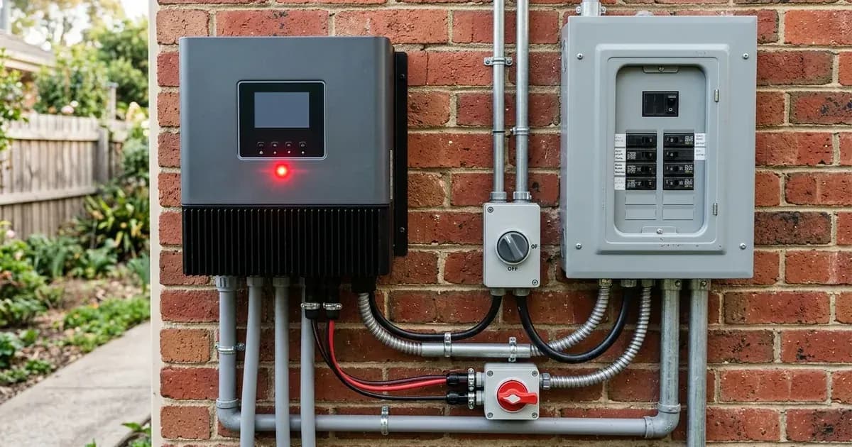
Solis S5-EH1P-L series hybrid inverters are designed to provide reliable solar energy conversion and storage. However, like all complex electronic systems, they can display error codes or fault messages on the LCD screen. Understanding these codes is the first step in diagnosing and resolving issues, minimizing system downtime.
This guide provides a comprehensive overview of common error codes for Solis S5 and S6 inverters, their meanings, and practical troubleshooting steps. We'll cover grid-related faults, PV input issues, battery system errors, and internal inverter malfunctions.
Safety First: Essential Precautions Before Troubleshooting
Before attempting any troubleshooting or maintenance on your Solis inverter, it is critical to prioritize safety. Electrical installations must always comply with local and national electrical safety standards.
Always observe the following safety guidelines:
- Qualified Personnel Only: Operations must be accomplished by licensed technicians or Solis authorized personnel.
- Personal Protective Equipment (PPE): Operator must put on the technicians’ gloves during the whole process in case of any electrical hazards.
- Power Isolation:
- Disconnect the inverter from the utility grid and the PV input.
- Do not touch any inner live parts until 5 minutes after disconnection from the utility grid and the PV input. This allows energy stored in capacitors to discharge.
- Do not remove the cover for 5 minutes after disconnecting all power sources.
- No User Serviceable Parts: There are no user serviceable parts inside. Refer servicing to qualified and accredited service technicians. Removing the cover without authorization may void the warranty.
- Hot Surfaces: The surface temperature of the inverter can reach up to 75℃ (167℉). To avoid risk of burns, do not touch the surface of the inverter while it’s operating. Turn OFF the inverter and let it cool down before any maintenance or cleaning.
- DC Reverse Connection: If DC inputs are accidentally reversely connected or the inverter is faulty, it is NOT allowed to turn off the DC switch immediately if the current is above 0.5A. Wait for the solar irradiance to reduce until the current decreases to below 0.5A. Only after the current is below 0.5A are you allowed to turn off the DC switches and disconnect the PV strings. Damages due to wrong operations are not covered in the device warranty.
- Fire Safety: Do not install the inverter in areas containing highly flammable materials or gases or in potentially explosive atmospheres. The mounting structure where the inverter is installed must be fireproof.
- Children: The inverter must be installed out of the reach of children.
- Cleaning: Never use any solvents, abrasives or corrosive materials to clean the inverter.
Understanding Solis Inverter Error Codes
Solis inverters display error codes on their LCD screen to indicate specific operational issues. These codes provide valuable clues for diagnosis. Some codes indicate a temporary condition that the inverter manages, while others point to a critical fault requiring intervention.
The troubleshooting suggestions provided in the inverter manual often include checking connections, verifying grid conditions, and restarting the system. If a fault persists after basic troubleshooting, contact Solis customer service or a qualified technician.
Grid-Related Faults
Grid-related faults occur when the inverter detects an abnormality in the utility grid's voltage or frequency, or issues with its connection to the grid. The inverter will often disconnect from the grid for safety and compliance with local grid codes.
Code in LCD | Meaning / Description | Troubleshooting Suggestion |
|---|---|---|
OV-G-V01 | Grid voltage exceeds the upper voltage range |
|
OV-G-V02 | Grid transient overvoltage |
|
OV-G-V03 | Grid transient overvoltage |
|
OV-G-V04 | Grid voltage exceeds the upper voltage range |
|
OV-G-V05 | Grid voltage RMS instantaneous overvoltage fault |
|
UN-G-V01 | Grid voltage exceeds the lower voltage range |
|
UN-G-V02 | Grid voltage exceeds the lower voltage range |
|
OV-G-F01 | Grid frequency exceeds the upper frequency range |
|
OV-G-F02 | Grid frequency exceeds the upper frequency range |
|
UN-G-F01 | Grid frequency exceeds the lower frequency range |
|
UN-G-F02 | Grid frequency exceeds the lower frequency range |
|
G-PHASE | Unbalanced grid voltage |
|
G-F-GLU | Grid voltage frequency fluctuation |
|
NO-Grid | No grid |
|
Surge Alarm | On-site grid surge |
|
IGFOL-F | Grid current tracking failure |
|
GRID-INTF02 | Power grid disturbance 02 |
|
Power Limitation Messages (Not Faults): These messages indicate the inverter is operating within parameters but limiting output due to grid conditions or internal settings.
Code in LCD | Meaning / Description | Troubleshooting Suggestion |
|---|---|---|
LmtByEPM | The device's output is under controlled |
|
LmtByDRM | DRM Function ON |
|
LmtByFreq | Frequency power limited |
|
LmtByVg | The device is in the Volt-Watt mode |
|
LmtByVar | The device is in the Volt-Var mode of operation |
|
LmtByUnFr | Under frequency limit |
|
PV Input Faults
These errors relate to issues with the solar panel array connected to the inverter, including overvoltage, ground faults, and leakage currents.
Code in LCD | Meaning / Description | Troubleshooting Suggestion |
|---|---|---|
OV-DC01 (1020 DATA:0001) | DC 1 input overvoltage |
|
OV-DC02 (1020 DATA:0002) | DC 2 input overvoltage |
|
PV ISO-PRO01 (1033 DATA:0001) | PV negative ground fault |
|
PV ISO-PRO02 (1033 DATA:0002) | PV positive ground fault |
|
ILeak-PRO01 (1034 DATA:0001) | Leakage current failure 01 (30mA) |
|
ILeak-PRO02 (1034 DATA:0002) | Leakage current failure 02 (60mA) |
|
ILeak-PRO03 (1034 DATA:0003) | Leakage current failure 03 (150mA) |
|
ILeak-PRO04 (1034 DATA:0004) | Leakage current failure 04 |
|
ILeak_Check (1039 DATA:0000) | Leakage current sensor failure |
|
AFCI-Check (1040 DATA:0000) | AFCI self-test failure |
|
ARC-FAULT (1041 DATA:0000) | AFCI failure |
|
Battery System Faults
These errors indicate problems with the connected battery bank, including connection issues, incorrect configuration, or voltage abnormalities.
Code in LCD | Meaning / Description | Troubleshooting Suggestion |
|---|---|---|
NO-Battery | Battery is not connected |
|
BatName-FAIL | Wrong battery brand selection |
|
CAN Fail | Can failure |
|
OV-Vbatt | Battery overvoltage detected |
|
UN-Vbatt | Battery undervoltage detected |
|
OV-Vbatt-H/OV-BUS-H (1051 DATA:0000) | Battery overvoltage hardware failure / VBUS |
|
Internal Inverter Faults
These codes point to issues within the inverter's hardware, software, or operational parameters. Many of these suggest contacting customer service if a simple restart does not resolve the issue.
Code in LCD | Meaning / Description | Troubleshooting Suggestion |
|---|---|---|
Off Control | device to shutdown |
|
OV-Vbackup | Inverting overvoltage |
|
Over-Load | Load overload fault |
|
LmtByTemp | Over temperature power limited |
|
Fan Alarm | Fan alarm |
|
OV-BUS (1021 DATA:0000) | DC bus overvoltage |
|
UN-BUS01 (1023 DATA:0001) | DC bus undervoltage |
|
UNB-BUS (1022 DATA:0000) | DC bus unbalanced voltage |
|
UN-BUS02 (1023 DATA:0002) | Abnormal detection of DC bus voltage |
|
DC-INTF. (1027 DATA:0000) | DC hardware overcurrent (1, 2, 3, 4) |
|
OV-G-I (1018 DATA:0000) | A phase RMS value overcurrent |
|
OV-DCA-I (1025 DATA:0000) | DC 1 average overcurrent |
|
OV-DCB-I (1026 DATA:0000) | DC 2 average overcurrent |
|
GRID-INTF. (1030 DATA:0000) | AC hardware overcurrent (abc phase) |
|
DCInj-FAULT (1037 DATA:0000) | The current DC component exceeds the limit |
|
IGBT-OV-I (1048 DATA:0000) | IGBT overcurrent |
|
OV-TEM (1032 DATA:0000) | Module over temperature |
|
UN-TEM (103A DATA:0000) | Low temperature protection |
|
12Power-FAULT (1038 DATA:0000) | 12V undervoltage failure |
|
RelayChk-FAIL (1035 DATA:0000) | Relay failure |
|
OV-ILLC (1052 DATA:0000) | LLC hardware overcurrent |
|
DSP-B-FAULT (1036 DATA:0000) | The master-slave DSP communication is abnormal |
|
INI-FAULT (1031 DATA:0000) | AD zero drift overlink |
|
General Troubleshooting Steps
For many error codes, the initial troubleshooting steps are similar:
- Check All Connections: Ensure all AC, DC, and communication cables are securely connected and free from damage. Pay particular attention to the AC cable for grid-related faults and battery cables for battery faults.
- Verify External Conditions:
- Grid: For grid faults, verify the stability of your utility grid. Check if other electrical devices in your property are experiencing issues.
- PV Array: For PV input faults, check the solar panels for shading, dirt, or physical damage.
- Battery: For battery faults, ensure the battery is charged and its voltage is within normal operating range.
- System Restart: Many faults can be cleared by a system restart. Follow the proper shutdown and startup procedure for your inverter.
- Turn off the AC breaker from the grid.
- Turn off the DC switch for the PV array.
- Turn off the battery breaker.
- Wait for 5 minutes to allow capacitors to discharge.
- Reverse the process to restart: Battery breaker on, DC switch on, AC breaker on.
- Consult the Manual: Always refer to your specific Solis inverter manual for the most detailed and up-to-date troubleshooting information.
- Contact Support: If the fault persists after performing basic troubleshooting, gather the error code, its description, and any troubleshooting steps you've already taken, then contact Solis customer service or a qualified technician.
FAQ: Solis S5 and S6 Inverter Error Codes
Q1: What should I do if my Solis inverter displays a grid voltage or frequency error (e.g., OV-G-V01, UN-G-F01)?
A1: These errors indicate that the grid voltage or frequency is outside the inverter's acceptable operating range, as defined by local safety regulations. First, confirm whether the power grid is abnormal by checking if other appliances are affected. Next, confirm that the AC cable is properly connected to the inverter and the grid. Finally, restart the system. If the fault persists, contact your utility provider or a qualified electrician.
Q2: My inverter shows "LmtByFreq" or "LmtByVg". Is this a fault?
A2: No, "LmtByFreq" (Frequency power limited) and "LmtByVg" (The device is in the Volt-Watt mode) are not typically fault codes but rather indications that the inverter is limiting its output power due to local safety regulations, often triggered by high grid voltage. The inverter is operating normally in these modes. If you need to close this mode due to factory test errors, you can do so via the LCD menu: Main menu → Advanced Settings → Password 0010 → STD mode settings → Working Mode → Working mode: NULL → Save and exit. Note that accessing advanced settings is for authorized technicians only, and improper operation may result in abnormal results and damage to the inverter, potentially voiding the warranty.
Q3: What does "PV ISO-PRO01" or "PV ISO-PRO02" mean, and how do I fix it?
A3: "PV ISO-PRO01" indicates a PV negative ground fault, while "PV ISO-PRO02" indicates a PV positive ground fault. Both point to insulation problems within your PV strings or damaged PV cables. To troubleshoot, you need to check the PV strings for insulation issues and inspect the PV cables for any damage. This often requires specialized equipment and expertise, so it's best handled by a qualified technician.
Q4: My inverter displays "Over-Load". What should I do?
A4: "Over-Load" (Load overload fault) means the backup load connected to the inverter is too large, or an inductive load has a high startup power. You need to remove some backup load or disconnect the inductive load from the backup output. The S5-EH1P-L Series does not support parallel (three- and single-phase) operation on the AC-BACKUP port, and connecting multiple units in parallel will void the warranty.
Q5: What if my Solis inverter shows "CAN Fail" or "BatName-FAIL"?
A5: "CAN Fail" indicates a communication failure between the inverter and the battery's Battery Management System (BMS). Check the CAN cable conditions, ensure it's plugged into the correct CAN port on both the battery and inverter, and verify you are using the right cable, as some batteries require a special cable from the battery manufacturer. "BatName-FAIL" means there's a wrong battery brand selection. Confirm that the battery model selected in the inverter settings is consistent with the actual battery installed. The inverter must be installed with compatible battery models. Any defect, damage or collateral loss due to using a non-compatible battery is not in the scope of inverter warranty or compensation.
Conclusion
Understanding the error codes displayed by your Solis S5 or S6 inverter is crucial for effective troubleshooting. While many issues can be resolved with basic checks and system restarts, always prioritize safety and consult qualified professionals for complex or persistent faults. Regular maintenance and adherence to installation guidelines can help prevent many common errors, ensuring the longevity and optimal performance of your solar energy system.
Still showing the fault? Book a technician
If the steps above did not clear it, tell us the inverter or battery and the exact code. We pass it to a technician who covers your city; visit charges are quoted before they come.
How this pays for the site: the technician or verifier pays SolarNevs a fixed introduction fee. Nobody pays to be recommended, and you are free to use our free guides instead.
Frequently asked questions
How do I clear faults on solis s5 s6 inverter error codes troubleshooting?
Isolate DC and AC power, wait 5 minutes for internal capacitors to discharge, verify connections, and restart the unit following manufacturer restart sequence.
Are these error codes universal across countries?
Hardware error codes and communication protocols are brand-global, but grid voltage and frequency trip thresholds are governed by regional standards.
References
- Solis Inverters S5 and S6 Troubleshooting Manual — accessed 27 August 2026
- Solis Inverter Alarm Codes — Complete List (official Solis/Ginlong support) — accessed 27 August 2026
Related guides
More from inverter errors & fixes.