Victron VE.Bus Error Codes: Troubleshooting MultiPlus, MultiPlus-II, and Quattro
Updated 7 September 2026 · By SolarNevs Research Desk, Dealer surveys + verified sources · 4 sources · Method ↗
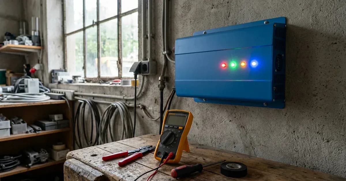
Victron Energy MultiPlus, MultiPlus-II, and Quattro inverter/chargers are central to many power systems, offering advanced features like parallel and three-phase operation. When issues arise, these devices communicate problems through VE.Bus error codes and LED indicators. Understanding these codes is crucial for quick diagnosis and resolution.
This guide provides a comprehensive overview of common Victron VE.Bus error codes (1-17), their meanings, and practical troubleshooting steps.
Understanding Victron VE.Bus Error Codes
The VE.Bus is Victron's communication protocol that allows multiple inverter/chargers to operate as a single, coordinated system. When a fault occurs within this network or a connected device, a specific VE.Bus error code is displayed, often accompanied by changes in the unit's LED status.
Safety Warning: Before performing any troubleshooting steps that involve inspecting or manipulating wiring, ensure all AC, DC, and PV power sources are isolated. Wait for the manufacturer's specified capacitor discharge time. Always use appropriate personal protective equipment (PPE) and insulated tools when working with electrical systems. Disconnecting terminals or working inside the enclosure should only be performed by qualified personnel.
Common VE.Bus Error Codes and Solutions
The following table details common VE.Bus error codes, their meaning, and recommended fix directions for MultiPlus, MultiPlus-II, and Quattro systems.
Code | Meaning | Fix Direction |
|---|---|---|
1 | Device is switched off because one of the other phases in the system has switched off. | Identify the failing phase (not showing Error 1) and check its LEDs for Overload, Low battery, or Temperature alarms. On a GX device, check the alarm status for each phase. On VRM, ensure automatic alarm monitoring is enabled to see Overload and Temperature errors. |
2 | New and old type MK2 protocol mixed in the system. | This should never happen. Contact Victron service. |
3 | Not all, or more than, the expected devices were found in the system. | Solve the cause for VE.Bus Error 1 if it preceded this error. Ensure all VE.Bus devices are configured as one system. Check communication cables for faults, using commercial patch leads. Check for blown DC fuses in any unit. |
4 | No other device found. | During a system restart, this can be temporary. If persistent, check communication cables for faults, avoiding self-made cables. The master device is configured for a parallel, split, or three-phase system but cannot find other devices. |
5 | Overvoltage on AC out. | Check the AC wiring of slave units to ensure they are properly connected. This problem can occur when the AC wiring of one of the slave units is not connected properly, or not connected at all. |
6 | Error in DDC Program (Assistant). | Update VE.Bus firmware in all devices to the latest version. Download the latest VEConfigure and Assistants, then re-configure the system. This error can also occur with a connected/disconnected VE.Bus BMS if the assistant is not configured accordingly. |
7 | External device connected, assistant required. | Configure the Multi/Quattro with a suitable Assistant for the connected external device (e.g., a VE.Bus BMS) if one is connected. |
8 | Ground relay test failed. | This error indicates a failed self-test of the MultiPlus-II or EasySolar-II internal ground relays. Check for external neutral-out to GND ties, intentional neutral bypasses (configure "Neutral path externally joined" grid-code if mandatory), leakage/short in loads, or faulty ground relay hardware. |
10 | System time synchronisation problem. | This typically happens during a system restart and is often not a real error. If persistent, check for a blown DC fuse in one or more units. |
11 | Relay Test Fault - Installation error or possibly relay failure. | Update units to the latest firmware. Verify proper wiring and local codes, especially the earth connection. Disconnect L and N wiring from ACout terminals to isolate loads. Check neutral-out connection for external ties. Check if neutral and line input are inverted. |
12 | Config mismatch with 2nd mcu. | Connect the device to VEConfigure 3, verify/correct settings, and press 'Send Settings', ensuring 'all settings' is selected. |
14 | Device cannot transmit data. | Check for a short circuit in communication cables. If not, it may be a broken component on the board, requiring repair. |
15 | VE.Bus combination error. | This can occur with incompatible VE.Bus products, firmware versions, or commands (e.g., old Interface-1140 with new Multi firmware, external BMS commands with VE.Bus BMS connected). Update firmware to the latest version. |
16 | VE.Bus dongle is missing. | Update firmware to the latest version; VE.Bus dongles are no longer necessary. |
17 | Phase master missing. | This error shows on slave units (only) when communication with the phase-master has timed out. |
Troubleshooting VE.Bus Communication
Many VE.Bus errors stem from communication issues. Proper wiring and cable management are critical for reliable system operation.
- Use Commercial Cabling: Always use industrially made network cabling. Using self-crimped RJ45 cables is a known cause of various errors.
- Daisy-Chain Correctly: All units must be daisy-chained with a VE.Bus cable (RJ-45 Cat5 or better). The sequence for daisy-chaining is not important.
- No Terminators: Do not use terminators in the VE.Bus network. The end-ports of the VE.Bus should be left open, or blanked out with no connection made.
- Optimal GX Connection: The optimal arrangement is a single RJ45 cable link from the GX device to the first VE.Bus inverter/charger, then daisy chain to subsequent VE.Bus inverter/chargers if they exist.
- Cable Separation: Maintain separation between power and communication cables. Bundling power and communication cables together should always be avoided. DC solar cables are the most likely to cause interference, followed by AC cables, then DC battery cables.
- Minimize Cable Lengths: Minimize communication cable lengths where possible and avoid bundling or coiling excess.
- Ferrite Cores: The use of Ferrite core noise suppressing cable clips can help filter out noise and should be installed on GX cables.
Diagnosing with LED Indicators
Victron inverter/chargers use LED sequences to provide diagnostic information, often complementing VE.Bus error codes. While the specific blink patterns for "Inverter On," "Mains On," "Bulk," "Absorption," "Float," "Overload," "Low Battery," and "Temperature alarm" are not detailed in this document, these LEDs are crucial for initial fault identification.
For detailed LED code definitions, refer to the Victron Toolkit App or the specific product manual. This app is designed to help interpret the various LED states and sequences for precise troubleshooting.
General Troubleshooting Steps
- Check DC Fuses: A blown DC fuse in one or more units can lead to communication errors (e.g., Error 3, Error 10).
- Firmware Updates: Ensure all VE.Bus devices have the latest firmware installed. This can resolve compatibility issues and DDC Program errors (e.g., Error 6, Error 15, Error 16).
- Verify AC Wiring: Incorrect or loose AC wiring, especially for slave units in multi-phase systems, can cause errors like Overvoltage on AC out (Error 5).
- Re-configure Assistants: If an external device (like a VE.Bus BMS) is connected, ensure the appropriate Assistant is loaded and configured in VEConfigure (e.g., Error 6, Error 7).
- Symmetrical Wiring: For units in parallel, both DC and AC wiring needs to be symmetrical per phase: use the same length, type, and cross-section to every unit in the phase. Use a bus-bar or power-post before and after the inverter/chargers to facilitate symmetrical wiring. Apply the same torque on all connections.
When to Contact Victron Service
If you have systematically worked through the troubleshooting steps and the error persists, or if you encounter an error not listed here (e.g., VE.Bus Error 2), it is recommended to contact Victron service or a qualified Victron installer. They have access to advanced diagnostic tools and can provide further assistance.
Still showing the fault? Book a technician
If the steps above did not clear it, tell us the inverter or battery and the exact code. We pass it to a technician who covers your city; visit charges are quoted before they come.
How this pays for the site: the technician or verifier pays SolarNevs a fixed introduction fee. Nobody pays to be recommended, and you are free to use our free guides instead.
Frequently asked questions
What is the main purpose of Victron VE.Bus Error Codes: Troubleshooting MultiPlus, MultiPlus-II, and Quattro?
It provides official Victron Energy configuration rules, technical parameters, and step-by-step troubleshooting procedures.
How do I resolve issues related to victron ve bus error codes?
Follow the documented verification steps, check wiring and firmware, and ensure all parameters match official Victron specifications.
References
- Victron Support: Ve.Bus - Manual Parallel And Three Phase Systems — accessed 27 August 2026
- Victron Support: Venus-Os - Remote Ve.Bus Firmware Updates — accessed 27 August 2026
- Victron Support: Ve.Bus - Ve.Bus Error Codes — accessed 27 August 2026
- Victron Support: Ve.Bus - Ve.Bus Network Interference — accessed 27 August 2026
Related guides
More from inverter errors & fixes.