Ziewnic Inverter Fault Light Meanings: No Output Troubleshooting
Updated 7 September 2026 · By SolarNevs Research Desk, Dealer surveys + verified sources · 4 sources · Method ↗
Key Takeaways
- A solid red fault light means the inverter has shut down due to a critical fault condition (codes 01–59); a flashing red light indicates a non-critical warning (codes 01–32).
- If the display is completely blank, the battery voltage is likely too low (below 1.4 V per cell) or the battery is connected with reversed polarity; when inspecting or disconnecting battery terminals, always kill power first and use insulated tools to prevent accidental shorts across a bank delivering hundreds of amps.
- Always disconnect and isolate all power sources (solar PV, battery DC, AC grid) and wait at least 5 minutes for internal capacitors to discharge before opening the enclosure or servicing terminal blocks.
- Internal component failures (such as bus voltage faults 08/09, inverter soft start fault 53, or current sensor fault 57) require professional repair at an authorized Ziewnic service center.
Why is my Ziewnic inverter showing a fault light and no output?
If your Ziewnic inverter is displaying a fault light and not providing AC output, it typically indicates a critical system error that has caused the inverter to shut down for protection. The most common causes are very low battery voltage preventing startup, an active fault condition like an overload or short circuit, or an internal component failure.
The first step is to observe the LED indicators on the front panel and check the LCD display for any specific fault or warning codes. These visual cues provide direct information about the inverter's status.
Diagnosis: Understanding Ziewnic Inverter Status Indicators
Follow these steps to diagnose why your Ziewnic inverter has no output or is showing a fault light.
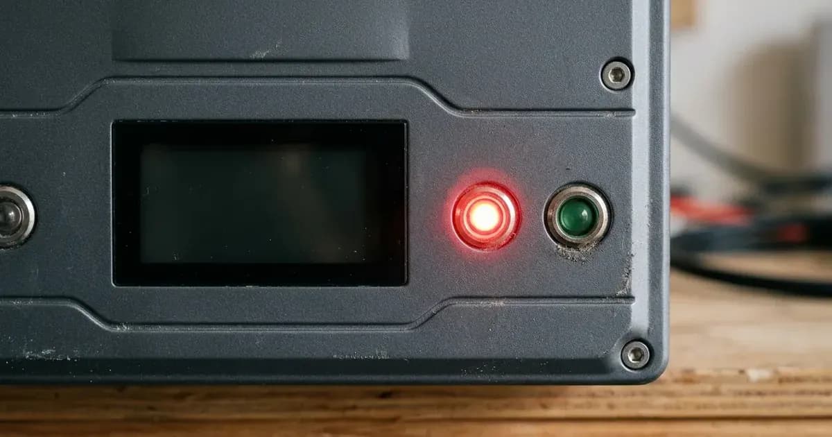
- Observe the Front Panel LEDs:
- Solid Red
FaultLED: This indicates a critical fault condition. The inverter has shut down its AC output. You should see a two-digit fault code (01–59) on the LCD display. - Flashing Red
FaultLED: This indicates a warning condition. The inverter is still operating, but an issue has been detected. A two-digit warning code (01–32) should be visible on the LCD. - No LEDs, Blank LCD, No Buzzer: This suggests a complete power loss or a severe battery issue.
- Green
LineLED: - Solid On: Output is powered by utility/grid.
- Flashing: Output is powered by battery or solar PV.
- Green
InverterLED: - Solid On: Inverter output is active and delivering power.
- Flashing: Inverter is synchronizing or transferring power sources.
- Green
ChargingLED: - Solid On: Battery is fully charged (in float stage).
- Flashing: Battery is actively charging.
- Solid Red
- Check the LCD Display for Fault or Warning Codes:
- If the
FaultLED is solid or flashing, the LCD should show a corresponding code. Refer to the "Ziewnic Inverter No Output Faults and Solutions" table below for common codes and their meanings. - If the LCD is blank, proceed to step 3.
- If the
- Measure Battery Voltage:
- Use a multimeter to measure the voltage across your battery bank terminals. CAUTION: When working near battery terminals, always disconnect and isolate all power sources (solar PV, battery DC, AC grid) and wait at least 5 minutes for internal capacitors to discharge. Use an insulated tool to prevent accidental shorts across a bank delivering hundreds of amps, causing severe burns or explosions.
- If the battery voltage is below 1.4 V per cell (e.g., <16.8 V for a 24 V bank or <33.6 V for a 48 V bank), the inverter will show no response at all.
- If the battery voltage is below 1.91 V per cell (e.g., <22.9 V for a 24 V bank or <45.8 V for a 48 V bank), the inverter may attempt to start (LCD/LEDs/buzzer for 3 seconds) but then shut down automatically.
- Ziewnic inverters require a minimum cold start voltage of 23.0 VDC for 24 V models and 46.0 VDC for 48 V models to initialize without AC grid assistance.
- Check AC Output Breaker:
- Ensure that the AC output breaker in your main distribution board (DB) or on the inverter itself is not tripped. A tripped breaker will prevent AC power from reaching your loads, even if the inverter is otherwise operational.
- Verify Inverter Operating Mode:
- Confirm that the power rocker switch on the bottom or side of the inverter is in the 'ON' position. If it's in 'OFF' (standby) mode, the LCD may display system metrics, but the inverter will not output power.
Ziewnic Inverter No Output Faults and Solutions
The following fault codes and troubleshooting steps apply to Ziewnic inverters built on the Voltronic OEM platform, including the Axpert Ultra, Axpert Twin Premium +, Diamond 5G/6G, and Max series. Identify your specific model series before applying troubleshooting steps, as touch-screen lines like Lenox and Roux feature different firmware and error structures.
Symptom detail | Likely cause | Fix |
|---|---|---|
Solid Red Fault LED with Fault 01 on LCD | Fan is locked when inverter is off | Shut down the inverter and isolate all sources (PV, battery, AC grid) and wait at least 5 minutes for internal capacitors to discharge before touching the fan or opening the housing; then Clean dust/obstructions from the fan grille; check fan connector; replace cooling fan if motor failed. |
Solid Red Fault LED with Fault 02 on LCD | Over temperature (internal heatsink >100 °C) | Check airflow clearances (>200 mm side, >500 mm top); clean anti-dust foam filter; reduce connected load. |
Solid Red Fault LED with Fault 03 on LCD | Battery voltage is too high (e.g., >33 V for 24 V, >63 V for 48 V) | Verify correct battery count (e.g., 2x12V or 4x12V); test individual cell voltages; check charge voltage settings (Program 26/27). |
Solid Red Fault LED with Fault 04 on LCD | Battery voltage is too low (e.g., <21.0 V for 24 V, <42.0 V for 48 V) | Re-charge batteries from solar/grid; test for dead/sulfated cells; increase low DC cut-off voltage in Program 29. |
Solid Red Fault LED with Fault 05 on LCD | Output short circuited | Turn off AC output breaker immediately; inspect AC load distribution board for shorts; clear the short circuit. |
Solid Red Fault LED with Fault 06 on LCD | Output voltage is too high (>260 VAC) | Reduce connected reactive load; restart inverter; if persistent, return to an authorized repair center. |
Solid Red Fault LED with Fault 07 on LCD | Overload time out (load ≥110% for 5 seconds, or 105%–110% load for 10 seconds) | Shed heavy appliances; reset unit; consider enabling overload bypass in Program 23. Refer to our guide on Ziewnic Overload Fault Fix. |
Solid Red Fault LED with Fault 08, 09, 53, or 57 on LCD | Internal component failure (Bus voltage too high/low, soft start failed, current sensor failed) | These indicate internal hardware issues. Power cycle the inverter once. If the fault persists, return the unit to an authorized Ziewnic service center. |
Solid Red Fault LED with Fault 51 on LCD | Over current or surge | Disconnect heavy inrush loads; restart unit. If the fault does not clear, output IGBT may be damaged, requiring professional repair. |
Solid Red Fault LED with Fault 58 on LCD | Output voltage is too low (<190 VAC) | Reduce load; inspect AC wiring; verify battery capacity. If unloaded voltage is low, return for service. |
Solid Red Fault LED with Fault 59 on LCD | PV open-circuit voltage exceeds your model's maximum PV VOC rating (400-500 VDC depending on model: 430 VDC on Diamond II 6G PV3000/PV4500, 400 VDC on Max Dual PV2500/PV5000, 450 VDC on Max PV7000, 500 VDC on Axpert Ultra and Diamond 5G/6G). | Reduce the number of solar panels wired in series per string; recalculate open-circuit voltage for extreme cold temperatures. |
Flashing Red Fault LED with Warning 01 on LCD | Fan is locked when inverter is on | Shut down the inverter and isolate all sources (PV, battery, AC grid) and wait at least 5 minutes for internal capacitors to discharge before touching the fan or opening the housing; then Clear dust from fan housing immediately; verify fan spin; replace fan before a thermal trip occurs. |
Flashing Red Fault LED with Warning 02 on LCD | Over temperature (elevated heatsink temp, approaching limit) | Improve ventilation; clean filter sponge; ensure no direct sunlight on the inverter body. |
Flashing Red Fault LED with Warning 04 on LCD | Low battery (approaching low DC cut-off) | Allow solar/grid to charge battery bank; reduce non-critical DC/AC loads during power outage. |
Flashing Red Fault LED with Warning 07 on LCD | Overload (load 100%-110% of rated capacity) | Reduce connected appliances before the 10-second overload countdown trips into a critical Fault 07. |
No display, no LEDs, no buzzer after power on | Battery voltage far too low (<1.4 V per cell) or reverse polarity | Check if battery wires are connected correctly. CAUTION: When checking or reconnecting battery terminals, always disconnect and isolate all power sources (solar PV, battery DC, AC grid) and wait at least 5 minutes for internal capacitors to discharge. Use an insulated tool to prevent accidental shorts across a bank delivering hundreds of amps, causing severe burns or explosions. Re-charge or replace the battery. |
LCD/LEDs/buzzer active for 3 seconds, then unit shuts off during startup | Battery voltage too low (<1.91 V per cell) | Re-charge or replace the battery. |
Inverter on, display active, but no AC output power | Active fault lockout (Fault 05, 07, 02, 51); Inverter in standby mode; Tripped output breaker | Clear active fault (if applicable); ensure power rocker switch is ON; reset AC output breaker. Refer to our guide on Inverter Shows Error But No Output. |
Ziewnic Inverter LED Status Indicators
Understanding the meaning of each LED on your Ziewnic inverter's front panel is crucial for quick diagnosis. Note that the following LED status indicators and meanings apply to Ziewnic inverters built on the Voltronic OEM platform, including the Axpert Ultra, Axpert Twin Premium +, Diamond 5G/6G, and Max series. These indicators provide a snapshot of the inverter's operational status.
LED Indicator | Color | Status | Meaning |
|---|---|---|---|
Line | Green | Solid On | The inverter's output is currently powered by the utility grid (WAPDA) in Line mode. |
Line | Green | Flashing | The inverter's output is currently powered by the battery bank or solar PV in Battery mode. |
Inverter | Green | Solid On | The inverter's internal power conversion bridge is active and successfully delivering power to connected loads. |
Inverter | Green | Flashing | The inverter is in the process of synchronizing with an incoming power source (like the grid) or is transferring between power sources. |
Charging | Green | Solid On | The battery bank connected to the inverter is fully charged and is currently in the float maintenance charging stage. |
Charging | Green | Flashing | The battery bank is actively undergoing a charging cycle, either in the bulk or constant voltage absorption stage. |
Fault | Red | Solid On | A critical fault condition has occurred within the inverter. The inverter has shut down its AC output to prevent damage. A specific fault code (01–59) will be displayed on the LCD. |
Fault | Red | Flashing | A warning condition has been detected. The inverter is still operating, but an issue requires attention. A specific warning code (01–32) will be displayed on the LCD. |
Safety: Working with Ziewnic Inverters
Working with solar inverters involves significant electrical hazards. Always prioritize safety.
- High-Voltage DC Shock Hazard: Ziewnic inverters handle high DC voltages from solar arrays. Single-phase models have Max VOC ratings up to 450-500 VDC depending on model (some Max Series units are limited to 400 VDC), while three-phase models like the Lenox 12 kW can reach up to 800 VDC. These voltages are lethal and can cause persistent DC arcing. Never touch exposed wires or terminals when the system is live.
- Internal Capacitor Stored Energy Discharge: Even after disconnecting all power sources (solar PV, battery DC, and AC grid), the inverter's internal DC bus capacitors retain a significant electrical charge. You must wait at least 5 minutes after disconnecting all power before opening the inverter enclosure or servicing any terminal blocks.
- Environmental Placement & IP Boundaries:
- Indoor models (e.g., Diamond II 6G, Axpert Ultra, Max Series, Roux Series) are rated IP21. They must be installed indoors in a clean, dry, well-ventilated area, protected from rain and direct water spray.
- Outdoor hybrid models (e.g., Lenox 3.0 series) are IP65 rated and suitable for outdoor wall mounting. Ensure the correct model is used for its intended environment.
- Anti-Dust Filter Kit Maintenance: Many Ziewnic inverters are equipped with anti-dust filter cases. The air filter sponges in these kits must be cleaned (washed or blown clear of dust) every 1 month. Neglecting this maintenance can restrict airflow, leading to thermal derating or Error 02 over-temperature trips.
When to call a technician instead
While many common issues can be resolved with basic troubleshooting, certain Ziewnic inverter faults require professional intervention. You should call a certified technician or Ziewnic's authorized service center if:
- The inverter displays fault codes related to internal component failures, such as Fault 08 (Bus voltage is too high), Fault 09 (Bus soft start failed), Fault 53 (Inverter soft start failed), or Fault 57 (Current sensor failed). These issues indicate a problem with the inverter's internal electronics that cannot be fixed by the user.
- The inverter consistently trips on overload (Fault 07) or over current (Fault 51) despite reducing connected loads and verifying wiring. This could indicate a deeper issue with the inverter's output stage.
- You have performed all basic troubleshooting steps, including checking battery voltage, wiring, and breakers, but the inverter remains unresponsive or continues to show a critical fault.
- The inverter is still under its 5-year PCBA replacement warranty (for flagship hybrid lines like Lenox) or standard 3 to 5-year warranty. Ziewnic's service centers are located in Karachi (Office # 5, 2nd floor, Above Meezan Bank, Rehman Mansion, Regal Chowk, Sharah-e-Liaquat, Saddar) and Lahore (51 Justice M. Akram (Mozang) Road, Near Masjid-e-Nimra, Near Saffa Wala Chowk).
For general inverter troubleshooting, you can also consult our comprehensive Inverter Error Code Glossary.
Still showing the fault? Book a technician
If the steps above did not clear it, tell us the inverter or battery and the exact code. We pass it to a technician who covers your city; visit charges are quoted before they come.
How this pays for the site: the technician or verifier pays SolarNevs a fixed introduction fee. Nobody pays to be recommended, and you are free to use our free guides instead.
Frequently asked questions
What does a solid red fault light mean on a Ziewnic inverter?
A solid red fault light indicates a critical fault condition, meaning the inverter has shut down its AC output. Before physically interacting with the inverter, always disconnect and isolate all power sources (solar PV, battery DC, AC grid) and wait at least 5 minutes for internal capacitors to discharge. Then, check the LCD display for a specific fault code (01–59) to identify the issue.
Why is my Ziewnic inverter display completely blank and not turning on?
A completely blank display with no LEDs or buzzer response typically means the battery voltage is far too low (below 1.4 V per cell) or the battery polarity is reversed. When checking or reconnecting battery terminals, always disconnect and isolate all power sources (solar PV, battery DC, AC grid) and wait at least 5 minutes for internal capacitors to discharge. Use an insulated tool to prevent accidental shorts across a bank delivering hundreds of amps, causing severe burns or explosions.
What does a flashing red light mean on a Ziewnic inverter?
A flashing red light indicates a warning condition. The inverter is still operating but has detected a non-critical issue. Before physically interacting with the inverter, always disconnect and isolate all power sources (solar PV, battery DC, AC grid) and wait at least 5 minutes for internal capacitors to discharge. Then, check the LCD display for a specific warning code (01–32) to understand the problem.
What is the minimum battery voltage for a Ziewnic inverter to start?
For automatic shutdown during startup, the battery voltage is too low below 1.91 V per cell. For no response at all, the voltage is below 1.4 V per cell. For a cold start without AC grid assistance, 24 V models require 23.0 VDC and 48 V models require 46.0 VDC.
My Ziewnic inverter is on and the display works, but there is no AC output. What could be wrong?
If the inverter is on but has no AC output, it could be due to an active fault lockout (e.g., overload, short circuit, over-temperature), the inverter being in standby mode (power rocker switch OFF), or a tripped AC output breaker in your distribution board.
References
- Ziewnic Official Web Portal — accessed 24 August 2026
- Ziewnic Product Page: AXPERT ULTRA (PV10000) — accessed 24 August 2026
- Ziewnic Product Page: 6G (PV3000) — accessed 24 August 2026
- Voltronic Power Axpert VM IV TWIN Off-Grid Manual (OEM platform for Axpert/Diamond/Max series) — accessed 24 August 2026
Related guides
More from inverter errors & fixes.