Solis Inverter Grid Voltage Alarms: OV-G-V and UN-G-V Triage Guide
Updated 18 September 2026 · By SolarNevs Research Desk, Dealer surveys + verified sources · 2 sources · Method ↗
Key Takeaways
- Alarm 1010 OV-G-V indicates grid voltage above statutory limits, while alarm 1011 UN-G-V indicates grid voltage below protective boundaries.
- If the inverter increases power up to 2000W and suddenly trips on OV-G-V1, line impedance and undersized AC cabling are causing localized volt rise.
- Always isolate AC and DC power before inspecting physical terminals, and make grid OFF in software before adjusting grid standards.
- Escalate persistent high grid voltage to your local distribution network operator to adjust local substation transformer tapping.
Why is my Solis inverter showing OV-G-V or UN-G-V?
Grid-tied solar inverters continuously monitor utility alternating-current voltage to protect household appliances and maintain network safety. In the manufacturer technical knowledge base, overvoltage events are categorized as 1010 - OV-G-V01 to 05, while undervoltage events appear as 1011 - UN-G-V.
By definition, UN-G-V means the grid voltages are lower than the protective value set in the inverter according to the local grid standard. Conversely, OV-G-V triggers when grid voltage exceeds the upper statutory envelope.
Frequency of occurrence provides the first diagnostic clue: if only one or two times a day then it is caused by the unstable grid. However, if the error occurs continuously or triggers specifically when solar generation increases, the issue is typically installation line impedance or an incorrect internal grid standard. For connection rules governing small embedded generation, consult our UK micro-generator connection guide.
Generation-onset tripping at 2000W and line impedance
A classic failure pattern on British domestic installations occurs on sunny afternoons: the inverter increases power up to 2000W and suddenly trips on OV-G-V1 error.
This symptom indicates an AC line impedance issue:
- As the inverter exports active power into the home and grid, current flows through the AC supply cable between the inverter and the consumer unit.
- If the AC cable run is exceptionally long, or if the conductor cross-sectional area is too small, electrical resistance produces a localized voltage rise (volt rise).
- The voltage at the inverter AC terminals rises until it trips the statutory overvoltage limit, while the main utility meter several rooms away remains within standard limits.
- To eliminate this issue, make sure cable length size and type should be according to our standard Solis manual, because problem also occurs due to line impedance issue.
Installers can verify line impedance behavior by running power throttling tests: check by power control 10%, 20%, and 50% to observe whether the inverter operates stably at reduced output.
Multimeter measurement and terminal voltage calibration
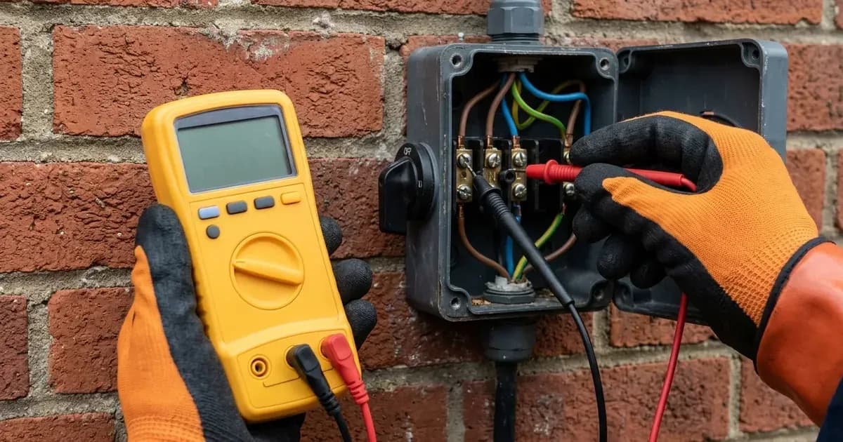
To verify whether the inverter voltage measurement circuit is accurate, electricians must compare internal telemetry against calibrated physical meter readings:
- Software Grid Disconnect: First make grid off from advance setting in inverter.
- Terminal Voltage Testing: Measure the grid voltages at the AC connectors to make sure there is voltage properly coming on connector.
- Compare Display with Reality: Please check the AC voltage both in the display as well as manually. Always check reading from inverter AC gland end.
- Calibration Delta: Voltage differences you must take after make grid OFF from inverter advance setting. If a discrepancy exists, calculate the display voltage and grid voltage difference and accordingly update the DSP.
- Physical Wiring Verification: If installation is new, check connectivity is proper of AC gland. Check the wire sequence inside of the AC connectors. If suspecting loose contact, properly connect the cable after disconnect from connector or ACDB.
For wider domestic electrical wiring standards, see our UK solar electrical installation guide.
Grid standard configuration protocol
Selecting the wrong regional grid code causes premature overvoltage tripping or prevents grid synchronization entirely:
- Check the grid standard and select right one like user-def or EN50438L or the required standard so that the fault does not occur again.
- Strict Configuration Order: You should change the standard after make grid OFF only; after standard change done, then only make Grid ON.
- Also check array insulation: use a multi-meter to check the voltages between PV+ and earth, PV- and earth of all the PV strings to confirm DC side health.
Maintaining stable grid export ensures uninterrupted payments under your Smart Export Guarantee agreement.
Safety rules for grid voltage diagnostics
Testing alternating-current supply lines involves live mains electricity:
- De-Energize Before Mechanical Work: Always switch off external AC rotary isolators and consumer unit breakers before opening connector housings or tightening terminal screws.
- Insulated Equipment: Voltage checks must be performed using calibrated multimeters and insulated test leads.
- Software Isolation First: Always disable the software grid switch (Grid OFF) before adjusting electrical protection parameters.
- Never Exceed Statutory Voltage Ceilings: Do not widen inverter overvoltage limits beyond approved distribution network boundaries without written authorization from your network operator. For commercial connections, see our UK commercial grid connection guide.
When to contact your local DNO
If manual multimeter testing at the main consumer unit confirms that incoming mains voltage exceeds statutory limits even when the solar inverter is completely turned off:
- The issue is high grid supply voltage on the external utility distribution network.
- Contact your regional Distribution Network Operator (via telephone 105 in England, Scotland, or Wales).
- Request a voltage investigation; the DNO can adjust the tap changer settings on the local distribution substation transformer to restore incoming supply to nominal levels.
Frequently asked questions
What does Solis alarm OV-G-V mean?
OV-G-V (alarm code 1010) indicates that utility grid voltage has risen above the protective threshold. If the fault happens only one or two times a day, it is usually caused by an unstable grid or local utility voltage fluctuations.
Why does my Solis inverter trip on OV-G-V1 when solar generation reaches 2000W?
If the inverter ramps power up to 2000W and suddenly trips on OV-G-V1, excessive AC line impedance is elevating local voltage at the terminals; confirm cable length, cable size, and conductor type against specification.
What causes a Solis UN-G-V alarm?
UN-G-V (alarm code 1011) means the grid voltages are lower than the protective value set in the inverter according to the local grid standard, indicating network dips or loose AC terminals.
How should an installer adjust the grid standard on a Solis inverter?
First make grid off from advance setting, then select the required compliant standard such as user-def or EN50438L; you should change the standard after making grid OFF only, then make Grid ON once complete.
References
- Solis Service Center 1010 OV-G-V01 to 05 Diagnostic Guide — accessed 15 September 2026
- Solis Service Center 1011 UN-G-V Troubleshooting Procedure — accessed 15 September 2026
Related guides
More from inverter errors & fixes.