Troubleshooting Victron VE.Bus Network Interference
Updated 9 September 2026 · By SolarNevs Research Desk, Dealer surveys + verified sources · 1 source · Method ↗
Key Takeaways
- Spurious VE.Bus errors are most often caused by electromagnetic interference from nearby power cables.
- The first troubleshooting step is to physically separate VE.Bus communication cables from all power cables.
- Always isolate all power sources (AC, DC, PV) before working on any system wiring.
- If errors persist after following all guidelines, or if you are unsure about electrical work, contact a qualified technician.
Why do I get spurious VE.Bus error codes on my Victron system?
Spurious VE.Bus error codes and communication issues on your Victron system are primarily caused by electromagnetic interference from power cables. This interference can disrupt the data signal, leading to unreliable system operation. The most common cause is insufficient physical separation between your VE.Bus communication cables and high-current power cables.
Diagnosis
Follow these steps to diagnose and identify potential sources of VE.Bus network interference in your Victron system.
- Check Cable Type:
- Observation: Are the VE.Bus cables manufactured cables, or were they crimped on-site?
- Meaning: On-site crimped cables significantly increase the risk of noise in the signal, even if they appear visually sound and test for continuity. Always use manufactured cables.
- Inspect Cable Routing and Separation:
- Observation: Are VE.Bus communication cables bundled with or running parallel to power cables (DC battery, AC, or DC solar cables)?
- Meaning: Bundling power and communication cables together is a major source of interference. Maintaining separation is critical. DC solar cables are the most likely to cause interference, followed by AC cables.
- Measure Cable Separation Distance:
- Observation: What is the approximate distance between your VE.Bus cables and any power cables?
- Meaning: Interference intensity drops sharply with distance. At 1 cm, interference is 100%. At 2 cm, it reduces to 25%. At 10 cm, it is only 1%, and at 20 cm, it falls to 0.25%, which is generally considered safe.
- Evaluate Cable Length and Coiling:
- Observation: Are VE.Bus cables excessively long, or is any excess cable coiled up?
- Meaning: Longer cable runs, especially when parallel to power cables, weaken the signal and increase noise. Coiling excess cable can also create an antenna effect, exacerbating interference. Minimize cable lengths and avoid coiling.
- Access Network Quality Counters:
- Observation: Check the network quality counters for your site on Victron Remote Management (VRM) by adding
/diagnosticsto the VRM URL (e.g.,https://vrm.victronenergy.com/site_id/diagnostics). - Meaning: These counters track communication errors. After commissioning a new system and performing a VE.Bus system reset on the GX device (in the Multi Advanced menu), the count should ideally be 0. If the counter is above 10, it indicates a problem with the physical installation. Note that some errors, like a missing Multi in a parallel system, may not increment these counters if the message is sent but the application level detects a missing device.
- Observation: Check the network quality counters for your site on Victron Remote Management (VRM) by adding
- Inspect Ferrite Core Clips:
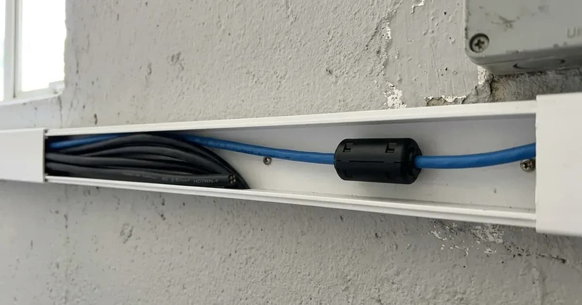
- Observation: Are ferrite core noise suppressing cable clips installed on your GX device cables? If errors persist, are they installed on other VE.Bus communication cables?
- Meaning: Ferrite core clips help filter out noise. They are supplied with GX devices for their cables. If VE.Bus network errors continue, installing them on each communication cable in the system at each connection point (between inverters, master inverter and GX, battery comms cables) can be beneficial.
- Verify VE.Bus Network Topology:
- Observation: How are your VE.Bus devices connected? Is it a simple daisy chain? Are there any loops or termination resistors?
- Meaning: The VE.Bus network is a bus topology. The optimal arrangement is a single RJ45 cable link from the GX device to the first VE.Bus inverter/charger, then daisy-chained to subsequent units. There should be no termination required at either end, and the end-ports should be left open or blanked out without any connection. Do not loop the cable back to these end points.
Cause/fix table
Symptom detail | Likely cause | Fix |
|---|---|---|
Spurious VE.Bus error codes | VE.Bus cable interference from power cables | Increase physical separation between VE.Bus cables and power cables. |
VE.Bus errors triggered by load types, load sizes, AC input connection/disconnection, temperature, physical disturbance, age, corrosion | VE.Bus cable interference | Improve cable routing, ensure adequate separation, and use manufactured cables. |
Increased noise to signal ratio in VE.Bus communication | On-site crimped cables | Always use manufactured VE.Bus cables; avoid crimping cables on-site. |
VE.Bus errors | Bundling power and comms cables together | Maintain strict separation; never bundle power and communication cables. |
Higher interference intensity (100% at 1 cm) | Data cables side by side with power cables at 1 cm | Increase separation to at least 10 cm (1% interference) or 20 cm (0.25% interference). |
Weaker signal and greater noise in communications cables | Longer cable runs, especially when in parallel with power cables | Minimize cable lengths; avoid coiling excess cable. |
Interference in VE.Bus network | DC solar cables | Prioritize separating VE.Bus cables from DC solar cables, as they are the most likely source of interference. |
Interference in VE.Bus network | AC cables | Ensure separation from AC cables, which are more likely to cause interference than DC battery cables. |
System shutdown and VE.Bus error (e.g., "Error 3") | Missing Multi in a parallel system (application level) | Verify all parallel inverter/chargers are correctly connected and communicating at the application level. |
High network error count (>10 post-commissioning) | Interference in the physical installation | Implement recommended cable separation, use manufactured cables, and consider installing ferrite core clips. Reset counters and re-evaluate. |
VE.Bus Network Best Practices
Adhering to best practices for your VE.Bus network cabling can prevent most interference issues.
- Use Manufactured Cables: Always use factory-manufactured VE.Bus cables. On-site crimped cables, even if they appear correct, can introduce significant noise into the communication signal.
- Maintain Separation: Physical separation between VE.Bus communication cables and all power cables (DC battery, AC, and especially DC solar cables) is paramount.
- At 1 cm separation, interference is 100%.
- At 10 cm separation, interference drops to 1%.
- At 20 cm separation, interference is typically considered safe at 0.25%.
- Avoid bundling power and communication cables together under any circumstances.
- Minimize Cable Lengths: Use the shortest possible manufactured VE.Bus cables for your installation. Avoid coiling any excess cable, as this can increase noise and weaken the signal.
- Identify Interference Sources: Be aware that DC solar cables are the most likely source of interference, followed by AC cables. Prioritize separating VE.Bus cables from these sources.
- Utilize Ferrite Core Clips: Ferrite core noise suppressing cable clips can help filter out electromagnetic noise. These are supplied with GX devices for their cables. If VE.Bus network errors persist despite proper cable routing, install ferrite core clips on each communication cable in the system at every connection point (e.g., between inverters, between the master inverter and the GX device, and on battery communication cables). The GX power supply ferrite can be installed with a loop to keep it secure.
- Correct Network Topology: The VE.Bus network uses a bus topology. The optimal arrangement is a single RJ45 cable link from the GX device to the first VE.Bus inverter/charger, then daisy-chained to any subsequent VE.Bus inverter/chargers. No termination is required at either end, and the end-ports of the VE.Bus should be left open or blanked out without any connection. Do not loop the cable back to these end points.
Safety
Working with solar power systems, especially inverter/chargers, involves high voltages and currents that can cause severe injury or death.
- Isolate All Power: Before inspecting or working on any wiring, including VE.Bus cables, ensure all power sources are completely isolated. This includes disconnecting AC input, DC battery connections, and PV (solar panel) input.
- Wait for Discharge: After disconnecting power, wait for the manual's specified capacitor discharge time before touching internal components or wiring.
- Use Insulated Tools: Always use properly insulated tools to prevent accidental short circuits or electrical shock.
- Avoid Short Circuits: A spanner or other metal tool across battery terminals or high-current busbars can cause hundreds of amps to flow, leading to severe burns, equipment damage, or fire.
When to call a technician instead
While many VE.Bus interference issues can be resolved with careful cable management, there are situations where professional help is necessary.
Call a qualified Victron technician if:
- VE.Bus errors persist despite thoroughly following all troubleshooting steps and implementing best practices for cable routing and separation.
- You are uncomfortable or unfamiliar with working on electrical systems involving high voltages and currents.
- The system exhibits erratic behavior, frequent shutdowns, or other symptoms that you cannot diagnose.
- You suspect internal damage to a Victron device. Opening the unit is authorized-service work and may void your warranty.
Frequently asked questions
What causes Victron VE.Bus errors?
Victron VE.Bus errors are frequently caused by electromagnetic interference from power cables running too close to the VE.Bus communication cables. On-site crimped cables and excessive cable lengths can also increase noise in the network.
How far should VE.Bus cables be from power cables?
To minimize interference, VE.Bus cables should be separated from power cables. At 1 cm, interference is 100%; at 10 cm, it reduces to 1%; and at 20 cm, it falls to 0.25%, which is usually considered safe.
How can I check the quality of my VE.Bus network?
You can access network quality counters via Victron Remote Management (VRM) by adding `/diagnostics` to your site's VRM URL. After commissioning and a VE.Bus system reset, these counters should ideally read 0. A count greater than 10 indicates a problem.
Can ferrite core clips help with VE.Bus interference?
Yes, ferrite core noise suppressing cable clips can help filter out noise. They are supplied with GX devices for GX cables, and if VE.Bus errors persist, they can be installed on each communication cable in the system at every connection point.
What is the correct topology for a VE.Bus network?
The VE.Bus network uses a bus topology. The optimal arrangement is a single RJ45 cable link from the GX device to the first VE.Bus inverter/charger, then daisy-chained to subsequent units. No termination is required, and end-ports should be left open.
References
- Victron Energy VE.Bus Network Interference Guide — accessed 23 August 2026
Related guides
More from inverter errors & fixes.