Victron AC Current Sensor Setup: Installation and Troubleshooting
Updated 8 September 2026 · By SolarNevs Research Desk, Dealer surveys + verified sources · 1 source · Method ↗
Key Takeaways
- The most common setup issue is incorrect firmware or an improper Multi/Quattro connection to the GX device.
- Always verify the dipswitch settings on the sensor match your expected PV inverter power range first.
- Before any wiring, always disconnect all power sources to prevent electrical shock.
- If basic checks and configuration steps do not resolve the issue, contact a qualified Victron technician.
Is your Victron AC Current Sensor not showing readings?
If your Victron AC Current Sensor is not displaying measurements, the most common causes are incorrect firmware versions on your Victron devices or an improper connection between your Multi or Quattro inverter/charger and the GX device. The first step is to check the physical connection and the dipswitch settings on the sensor itself.
Diagnosis: Step-by-Step Checks
- Verify Multi/Quattro Connection to GX Device:
- Check: Ensure your Multi or Quattro inverter/charger is connected to the VE.Bus port of your Color Control GX device.
- Result: If connected via the VE.Can port using a VE.Bus to VE.Can interface cable, the sensor readout will not work.
- Action: Reconnect the Multi or Quattro to the VE.Bus port if necessary.
- Check Multi/Quattro Firmware:
- Check: Confirm that the firmware in your Multi or Quattro inverter/charger is version 2xx or later. Also, verify that the 7-digit firmware version number on the microprocessor starts with 26 or 27.
- Result: Older firmware versions may not support the AC Current Sensor.
- Action: Update your inverter/charger firmware if it does not meet these requirements. (Note: Specific instructions for firmware updates are not detailed in the provided documentation.)
- Inspect GX Device Firmware:
- Check: Ensure your GX device is running firmware version v1.30 minimum, though a more recent version is recommended.
- Result: Outdated GX device firmware can cause compatibility issues.
- Action: Update your GX device firmware if it is older than v1.30.
- Confirm Sensor Wiring:
- Check: The AC Current Sensor must be wired to either the AUX input or the Temperature-input of your Multi or Quattro inverter/charger. For Multiplus-II hardware revisions 0 to 8, the AUX input is on RJ12 connector pins 1 and 5.
- Result: Incorrect wiring will prevent the sensor from communicating.
- Action: Verify the sensor is correctly connected to the designated AUX or Temperature input.
- Verify Dipswitch Configuration:
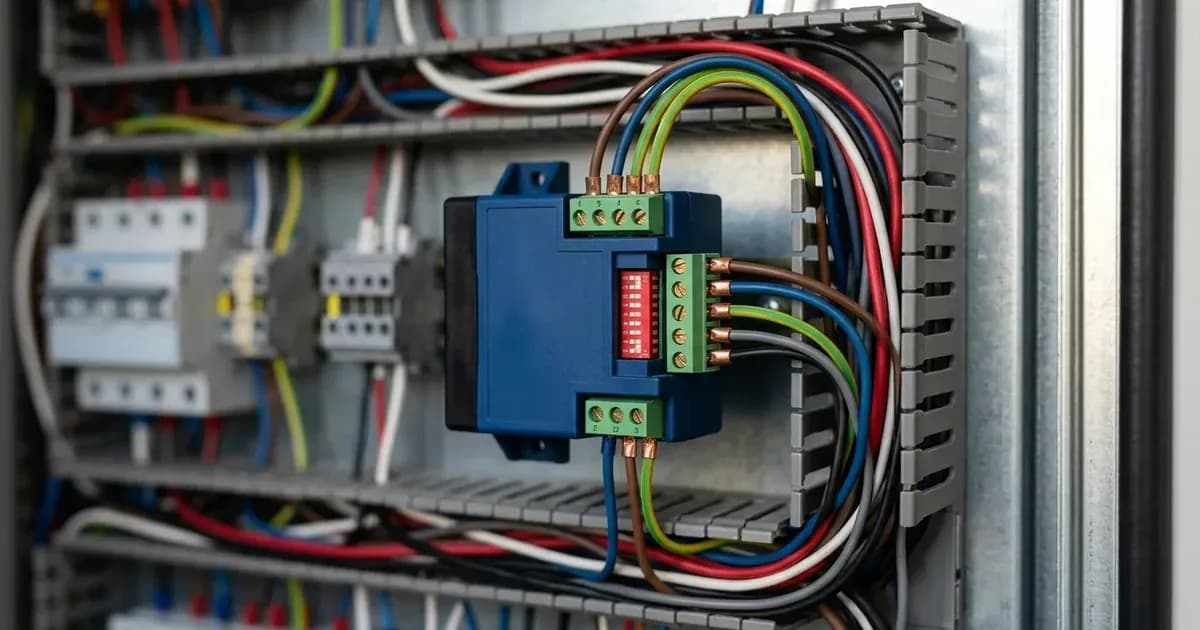
- Check: The dipswitches on the AC Current Sensor configure its power range. Ensure these are set correctly for your PV inverter's maximum expected power.
- Result: An incorrect power range setting can lead to inaccurate or no readings.
- Action: Adjust dipswitches according to the power range table below.
- Check GX Device System Setup Profile:
- Check: On your GX device, navigate to
Settings → System setupand ensure the correct profile is selected. (Note: The specific "correct profile" is not detailed in the provided documentation.) - Result: An incorrect system profile can prevent proper integration.
- Action: Select the appropriate system profile for your setup.
- Check: On your GX device, navigate to
Troubleshooting Table
Symptom detail | Likely cause | Fix |
|---|---|---|
No readings on GX device | Multi/Quattro connected to VE.Can port of Color Control GX | Reconnect Multi/Quattro to the VE.Bus port of the Color Control GX. |
No readings or incorrect values | Multi/Quattro firmware is too old | Update Multi/Quattro firmware to 2xx or later, with microprocessor firmware starting with 26 or 27. |
No readings or incorrect values | GX device firmware is too old | Update GX device firmware to v1.30 minimum (more recent recommended). |
Inaccurate or no power readings | Incorrect dipswitch setting for power range | Adjust dipswitches to select a power range equal to or higher than the maximum expected power. |
Sensor not detected | Incorrect wiring to Multi/Quattro | Ensure sensor is wired to the AUX input or Temperature-input of the Multi/Quattro. |
Readings not appearing | Incorrect system profile selected on GX device | Select the correct system profile under |
Configuration and Setup Details
The Victron AC Current Sensor is designed to measure and visualize the solar production from a PV Inverter when integrated into a Victron Energy system.
Power Range Configuration
The sensor's power range must be configured using its dipswitches. You should select a power range that is equal to or higher than the maximum expected power from your PV inverter. The available power ranges and their corresponding dipswitch settings are:
Power range | Max measured Current | Max Input current | Dipswitch |
|---|---|---|---|
1.5 kW | 8 A | 9 A | all off |
3 kW | 16 A | 18 A | 1 |
5 kW | 25 A | 30 A | 1,2 |
7 kW | 30.5 A | 40 A | 1,2,3 |
The sensor has an IP54 protection category, indicating it is protected against dust ingress and splashing water. A maximum of 9 sensors can be used in one system.
Firmware Requirements
For proper operation, ensure your Victron devices meet the following firmware criteria:
- Multi or Quattro Inverter/Charger: Firmware version 2xx or later. The 7-digit firmware version number on the microprocessor must start with 26 or 27.
- GX Device: Minimum firmware version v1.30. Running a more recent version is recommended for optimal performance and compatibility.
Connection Points
The AC Current Sensor connects directly to your Multi or Quattro inverter/charger. It can be wired to either the AUX input or the Temperature-input. For Multiplus-II hardware revisions 0 to 8, the AUX input is specifically located on RJ12 connector pins 1 and 5.
System Configuration Steps
For systems with parallel or three-phase operation, follow these steps:
- Configure Parallel or Three-Phase Operation: This must be done first before adding the sensor assistant.
- Add Assistant to Each Unit: Add the 'AC Current sensor' assistant using VEConfigure3 to each Multi or Quattro that has an AC Current Sensor connected.
- Select GX Device Profile: On the GX device, go to
Settings → System setupand select the correct profile for your system.
Compatibility
The AC Current Sensor is compatible with a range of Victron MultiPlus and Quattro models. Some examples of compatible models with their minimum serial numbers for AUX and TEMP inputs include:
Product Code | Description | AUX input Minimum SN# | TEMP input Minimum SN# |
|---|---|---|---|
PMP123021010 | MultiPlus 12/3000/120-50 - 230V | HQ1352 | All serial numbers |
PMP243021010 | MultiPlus 24/3000/70-50 230V | HQ1350 | All serial numbers |
PMP485021010 | MultiPlus 48/5000/70-100 230V | HQ1326 | All serial numbers |
QUA123020010 | Quattro 12/3000/120-50/50-230V | HQ1332 | All serial numbers |
QUA485021010 | Quattro 48/5000/70-100/100-230V +50A aux. | HQ1330 | All serial numbers |
PMP243021014 | Multi-G 24/3000/70-50 | All serial numbers | All serial numbers |
Many other models are also compatible, often with "All serial numbers" for both AUX and TEMP inputs.
Safety Considerations
Working with electrical systems carries inherent risks. Always prioritize safety:
- Disconnect Power: Before performing any wiring or inspection, ensure all AC and DC power sources to the inverter/charger and associated equipment are completely disconnected and locked out. Verify zero voltage with a multimeter.
- Qualified Personnel: If you are not comfortable or experienced with electrical wiring, consult a qualified electrician or Victron Energy installer.
- Insulated Tools: Use insulated tools to prevent accidental short circuits.
- Protection: The AC Current Sensor itself has an IP54 protection category, meaning it is protected against dust and splashing water. Ensure its installation environment respects this rating.
When to call a technician instead
While many setup issues can be resolved with basic troubleshooting, there are situations where professional assistance is necessary:
- Persistent Issues: If you have followed all diagnostic steps and the sensor still does not function correctly or provides inaccurate readings.
- Complex Wiring: If your system involves complex multi-phase or parallel inverter setups, or if you are unsure about the correct wiring to the AUX or Temperature inputs.
- Firmware Update Difficulties: If you encounter problems updating the firmware on your Multi/Quattro or GX device.
- Warranty Concerns: Attempting repairs beyond basic configuration may void your product warranty. Consult your Victron Energy dealer or a certified technician for advanced diagnostics and repairs.
Frequently asked questions
What is the Victron AC Current Sensor used for?
The Victron AC Current Sensor is used to measure and visualize the solar production of a PV Inverter. It integrates with Victron Multi and Quattro inverter/chargers and GX devices.
How do I configure the power range on a Victron AC Current Sensor?
You configure the power range using the dipswitches on the sensor. Select a power range that is equal to or higher than the maximum expected power from your PV inverter. Available ranges include 1.5 kW, 3 kW, 5 kW, and 7 kW.
What firmware is required for my Victron Multi or Quattro to use the AC Current Sensor?
Your Multi or Quattro inverter/charger requires firmware version 2xx or later. Additionally, the microprocessor firmware number, found on the microprocessor itself, must start with 26 or 27.
Why is my Victron AC Current Sensor not showing readings on my GX device?
A common cause is connecting your Multi or Quattro to the VE.Can port using a VE.Bus to VE.Can interface cable. The Multi or Quattro must be connected to the VE.Bus port of the Color Control GX for the sensor readout to function.
Where can I see the measurements from my Victron AC Current Sensor?
The measurements from the AC Current Sensor will be visible on your Victron GX device and can also be monitored remotely through the Victron VRM Portal.
References
- Victron Energy AC Current sensor product page — accessed 23 August 2026
Related guides
More from inverter errors & fixes.