Sunsynk Eastron Meter vs CT Clamp: When to Use Which
Updated 16 September 2026 · By SolarNevs Research Desk, Dealer surveys + verified sources · 15 sources · Method ↗
Key Takeaways
- An Eastron meter is required if the CT clamp cable length exceeds 15 metres, or if you need to read PV data from a string inverter.
- Different Eastron meter models (SDM120CT, SDM230, SDM630MCT) have specific compatibility and wiring requirements based on your Sunsynk inverter type and phase configuration.
- Incorrect meter selection, wiring, or inverter settings can lead to a
W04 Meter Comm Failerror or inaccurate readings. - All wiring and configuration of external meters and CT clamps on the grid side must be performed by a registered person to ensure safety and compliance with NRS 097-2-1.
When to use an Eastron Meter instead of a CT Clamp
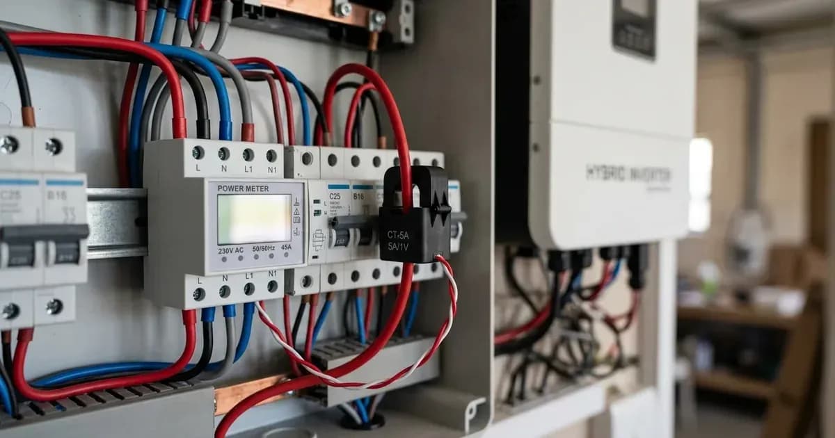
Sunsynk inverters rely on current transformer (CT) clamps or external meters to accurately measure grid-side energy flow. While CT clamps are common, there are specific situations where an Eastron meter becomes necessary.
The primary reason to use an Eastron meter is cable length. The cable length between the inverter and the CT clamp should ideally be no more than 10 metres. While it can be extended up to 15 metres in some circumstances, anything longer than this requires an Eastron meter to obtain accurate power values. This is particularly relevant in South African installations where the distribution board (DB) and inverter may be far apart.
An Eastron meter can also be used to read PV data from a string inverter, allowing the Sunsynk hybrid inverter to manage the overall system more effectively.
Understanding Eastron Meter Models
Sunsynk inverters are compatible with several Eastron meter models, each with specific applications and configurations. Selecting the correct meter and understanding its settings is crucial for accurate system operation.
Eastron SDM120CT Series
This single-phase meter is supplied with its own 120A / 40mA CT coil and is not compatible with the standard Sunsynk 100A / 50mA CT coil. The Eastron CT coil has a ratio of 3000:1, while the Sunsynk CT coil is 2000:1. This meter is not compatible with three-phase inverters. No settings changes are typically needed for the SDM120CTM model, as it comes preconfigured.
Eastron SDM230 Series
This is another single-phase meter, also not compatible with three-phase inverters. It requires specific communication settings to be configured.
Eastron SDM630MCT and SDM630MCT v2
These are three-phase meters, suitable for both single-phase and three-phase Sunsynk inverters, depending on the wiring. The SDM630MCT and its v2 variant have slight differences in their CT configuration settings. Both are compatible with CTs that have a 1A or 5A secondary current.
Meter Model | CT Setting (SDM630MCT) | CT Setting (SDM630MCT v2) | Description |
|---|---|---|---|
SDM630MCT | | N/A | Set to the primary current of your CT coil. |
SDM630MCT | | | Set to the secondary current of your CT coil (1A or 5A ONLY). |
SDM630MCT v2 | N/A | | Set for the CT ratio (Primary/Secondary). |
The default password for entering setup mode on both the Eastron SDM630MCT and SDM230 meters is 1000.
Configuring Eastron Meters for Sunsynk Inverters
Proper wiring and inverter settings are essential for an Eastron meter to communicate correctly with your Sunsynk inverter. Incorrect setup can lead to a W04 Meter Comm Fail warning.
General Inverter Settings for External Meters
For Classic, Acure, and Elite series inverters, you must enable Ex_Meter_for_CT in the inverter's Advanced Settings. Then, in Meter Select, choose the matching meter type (e.g., Eastron 1P, Eastron 3P).
Single-Phase Inverter with Single-Phase Eastron Meter (SDM120CT series)
- Wiring Power: Wire the live supply into port 4 and the neutral supply into port 3 of the Eastron meter.
- CT Coil Connection: Connect the CT coil, wiring black into port 2 and white into port 1.
- RS485 Connection: Connect a CAT-5/6 cable: solid blue to RS485-B (port 9) and blue/white to RS485-A (port 10) on the meter.
- Inverter Connection: On the inverter side, connect the solid blue cable into pin 4 and the blue/white cable into pin 5 of the RJ45 plug for most inverter models. For 10kW, 12kW, or 16kW inverters, use pins 1 and 2 in the RJ45 plug.
Single-Phase Inverter with Single-Phase Eastron Meter (SDM230 series)
- RS485 Connection: Connect a CAT-5/6 cable: solid blue to RS485-B (port 6) and blue/white to RS485-A (port 5) on the meter.
- Meter Settings: The Eastron SDM230 requires specific communication settings:
Address: 001,Baud Rate: 9.6k, andParity: None. The password to change meter settings is1000.
Single-Phase Inverter with Three-Phase Eastron Meter (SDM630MCT)
This setup is used when a single-phase inverter needs to monitor a three-phase supply.
- Wiring Power: Create a bridge from connection 5 (LA) to phase 1 (connection 4) and from connection 6 (NA) to the neutral (connection 1) on the Eastron meter.
- CT Clamp Placement: The CT clamp must be placed on the live supply tail coming from the property's main meter, with the arrow pointing towards the loads (distribution board).
- CT Clamp Connection: Connect the white cable into S1 1 and the black cable into S2 1 on the Eastron meter.
- RS485 Connection: Connect a CAT-5/6 cable: a solid coloured cable (e.g., brown) to TX+A (connection 14) and its corresponding colour/white cable (e.g., brown/white) to TX-B (connection 13).
- Inverter Connection: For 3.6kW and 5kW Ecco inverter units, connect Pin 4 to 485-B and Pin 5 to 485-A on the RJ45 plug, then plug into the inverter's Meter/RS485 Port.
Three-Phase Inverter with Three-Phase Eastron Meter (SDM630MCT)
This setup applies to Classic three-phase low-voltage inverter units (8kW, 10kW, 12kW).
- Wiring Power: Create a bridge from connection 5 (LA) to one of the phases (connection 2, 3, or 4) and from connection 6 (NA) to the neutral (connection 1).
- CT Clamp Placement: The CT clamps must be placed on the live supply tails from the incoming supply, with the arrow pointing towards the loads (distribution board).
- RS485 Connection: Similar to the single-phase setup, connect a solid coloured cable to TX+A (connection 14) and its corresponding colour/white cable to TX-B (connection 13).
- Inverter Connection: For 8kW, 10kW, and 12kW three-phase low-voltage inverter units, connect Pin 4 to 485-B and Pin 5 to 485-A on the RJ45 plug, then plug into the inverter's Meter/RS485 Port.
Lifelynk XL Inverters with Eastron Meters
For Lifelynk XL inverters, the Smart Meter mode needs to be enabled in the inverter's Advanced Settings.
- Wiring Power: Wire the live supply into port 4 (L1) and the neutral supply into port 1 (N). Create a bridge between port 1 (N) and port 6 (NA), and between port 4 (L1) and port 5 (LA).
- CT Coil Connection: Connect the CT coil, black into Port 19 (1-S2) and white into port 20 (1-S1).
- RS485 Connection: Connect a CAT-5/6 cable: blue/white to port 14 (TX+A) and blue to port 13 (TX-B).
- Inverter Connection: On the other end of the CAT-5 cable, use an RJ45 connector and slot the blue cable into pin 4 and the blue/white cable into pin 5.
String Inverter with Eastron Meter
For string inverters, the enable meter setting will need to be ON. The password for the string inverter is 1234.
Advanced Configurations: Two Meters or PV Data
Using Two Eastron Meters on One System
It is possible to use two Eastron meters on a single Sunsynk system, typically one for grid monitoring and one for PV generation from a string inverter.
- Modbus Addresses: The Eastron meter for grid monitoring must have its Modbus address set to
1. The second Eastron meter, used for PV data, must have its Modbus address set to2. - Inverter Settings: Once both meters are connected,
Ex_Meter for CTandGrid Tie Meter 2must be enabled in the inverter settings. The meter type must be set toEastron. - Specialised Software: Sunsynk states that using two Eastron meters on one system requires a specialised software version. Contact Sunsynk Support for guidance.
Reading String Inverter PV Data through an Eastron Meter
This setup allows a Sunsynk hybrid inverter to monitor the output of a separate string inverter via an Eastron meter.
- Inverter Settings: Enable
GridTieMeter2in the advanced settings page and selectEastron 3Pin theMeter Selectdrop-down menu. Also, enableAC Couple on Grid Sidein the auxiliary settings. - Eastron Power Wiring: Double up the neutral to NA and L1 to LA to power on the Eastron meter.
- CT Clamp Placement: The CTs must be clamped on the live supply tails coming out of the string inverter, with the arrows pointing away from the string inverter towards the distribution board.
What you can change yourself, and what you cannot
As an owner, you can monitor your system's performance and check for error codes like W04 Meter Comm Fail. However, any physical wiring, installation, or modification of CT clamps or Eastron meters on the grid side of your electrical system requires a registered person. This includes placing CT clamps, connecting meters, and configuring grid-protection settings.
Incorrect installation or configuration can lead to inaccurate readings, system malfunctions, or safety hazards. In South Africa, such work must comply with NRS 097-2-1 and be certified by a Certificate of Compliance (CoC). Attempting to modify these settings or wiring without proper qualifications can invalidate your CoC and pose a risk to yourself and the electrical grid.
What the published sources do not tell you
The Sunsynk documentation provides detailed wiring diagrams and settings for various Eastron meter configurations. However, it does not provide specific pin-out definitions for all inverter models, often referring to the user manual for specific details.
The documentation also mentions that a "specialised software version" is required for using two Eastron meters on one system, but does not provide details on how to obtain or verify this software version. Similarly, it states that an "override password" may be needed for Eastron CT ratio settings if further changes are required, but does not provide this password or guidance on obtaining it.
While the documentation references UK grid standards like G98/G99 and G100 for compliance, these are not applicable in South Africa. South African installations must adhere to NRS 097-2-1. The documentation does not provide specific guidance on how Eastron meters or Sunsynk inverters comply with NRS 097-2-1.
Frequently asked questions
When should I use an Eastron meter instead of a CT clamp with my Sunsynk inverter?
You should use an Eastron meter if the cable length between your Sunsynk inverter and the CT clamp exceeds 15 metres. CT clamp cables are ideally no more than 10 metres, but can be extended up to 15 metres.
What is the difference between the Eastron SDM630MCT and SDM630MCT v2 meters?
The primary difference is how they handle CT settings. The SDM630MCT uses `CT1` for primary current and `CT2` for secondary current (1A or 5A). The SDM630MCT v2 uses `CT2` for secondary current (1A or 5A) and a dedicated `CT Rate` setting for the CT ratio.
Can I use two Eastron meters on one Sunsynk system?
Yes, it is possible to use two Eastron meters on one system, typically one for grid data and one for PV data. This requires setting different Modbus addresses for each meter (1 for grid, 2 for PV) and enabling specific settings in the inverter.
What does a W04 Meter Comm Fail error mean on a Sunsynk inverter?
A W04 Meter Comm Fail error indicates a communication failure with an external meter. This can be caused by incorrect wiring, incorrect meter settings, or issues with the RS485 data cable.
Are Eastron meters compatible with all Sunsynk inverter types?
Eastron meters have specific compatibility. For example, the SDM120CT series and SDM230 series are not compatible with three-phase inverters. Always verify the specific Eastron model's compatibility with your Sunsynk inverter type.
References
- Sunsynk Support — Classic/Acure/Elite Single Phase Eastron Meter with Single Phase Inverter (SDM120CT series) — accessed 27 August 2026
- Sunsynk Support — Classic/Acure/Elite Using an Eastron Meter to Read String Inverter PV Data — accessed 27 August 2026
- Sunsynk Support — Export Issues — accessed 27 August 2026
- Sunsynk Support — No Grid-Side Load Readings — accessed 27 August 2026
- Sunsynk Support — Acure External Meters — accessed 27 August 2026
- Sunsynk Support — CT Clamp Guide — accessed 27 August 2026
- Sunsynk Support — Eastron Meters CT Selection and Settings — accessed 27 August 2026
- Sunsynk Support — Classic/Acure/Elite Single Phase Eastron Meter with Single Phase Inverter (SDM230) — accessed 27 August 2026
- Sunsynk Support — Classic/Acure/Elite Three Phase Eastron Meter with Single Phase Inverter — accessed 27 August 2026
- Sunsynk Support — SDM630MCT vs SDM630MCT v2 — accessed 27 August 2026
- Sunsynk Support — Classic/Acure/Elite Using 2 Eastron Meters on One System — accessed 27 August 2026
- Sunsynk Support — Lifelynk External Meters — accessed 27 August 2026
- Sunsynk Support — String Inverter Eastron Meters — accessed 27 August 2026
- Sunsynk Support — Classic Three Phase Eastron Meter with Three Phase Inverter — accessed 27 August 2026
- Sunsynk Support — W04 Troubleshooting — accessed 27 August 2026
Related guides
More from sizing, net billing & installation.