Solis Inverter Loss of Mains & Grid Interference Troubleshooting (Ireland)
Updated 19 September 2026 · By SolarNevs Research Desk, Dealer surveys + verified sources · 3 sources · Method ↗
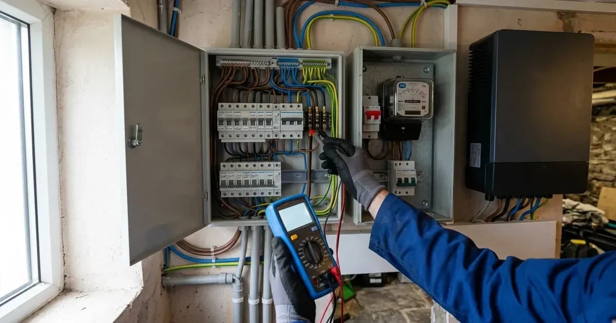
When a Solis solar inverter installed on the Irish electricity network trips with alarm code 1030 (GRID-INTF), the unit has detected abnormal grid interference or an apparent loss-of-mains condition. Under Irish microgeneration rules mandated by ESB Networks and the Commission for Regulation of Utilities (CRU), every grid-parallel inverter must continuously monitor utility AC power quality. Inverters installed in Ireland must comply with EN50549 with Irish Protection Settings to ensure immediate anti-islanding disconnection whenever utility supply becomes unstable or disconnects.
When grid voltage waveforms deteriorate, frequency drifts, or local line impedance shifts abruptly due to heavy switching loads, the inverter's internal digital signal processor halts active generation to protect utility lineworkers from energized islanded circuits. Diagnosing whether the 1030 event represents a momentary local ESB distribution fluctuation, an internal filter setting mismatch, or a physical wiring defect requires systematic verification.
1. Initial Triage: Transient Utility Disturbances vs Continuous Faults
The diagnostic approach depends on how frequently the GRID-INTF alarm triggers during normal daylight operation:
- Transient Occurrences (1 to 2 times daily): If the error happens only once or twice a day, it is typically caused by temporary instability on the local ESB Networks low-voltage distribution line. Nearby industrial operations, agricultural equipment, heat pumps, or network switching events can inject brief harmonic spikes or voltage dips that prompt a defensive trip. The inverter automatically attempts reconnection once grid parameters stabilize.
- Persistent or Continuous Faults: If the error is continuous, active troubleshooting is required. Homeowners and electricians should begin with a controlled 30-minute system discharge to clear volatile digital memory.
[!WARNING]Disconnecting an inverter under high solar generation creates severe DC and AC arc hazards. Always open the external AC rotary isolator first, open the DC string isolator switch second, and wait at least 15 minutes for internal high-voltage electrolytic bus capacitors to discharge below touch-safe potentials before inspecting terminals.
To perform a complete microprocessor reset, shut down the AC isolator, open the DC isolator, and discharge the inverter for 30 minutes. If the inverter returns to normal operation after restoring power, the trip was caused by a transient grid anomaly. If the 1030 alarm re-engages immediately upon countdown completion, proceed to physical terminal and wiring inspections.
2. AC Connection & Gland Integrity Inspection
Physical connection defects between the inverter chassis and the consumer unit are common causes of artificial phase imbalance and waveform distortion:
- AC Gland Polarity: On new installations, verify that the AC cable is terminated correctly in the plug-in connector terminal. Polarity designations are embossed directly on the AC gland assembly. Reversing live and neutral conductors or landing the neutral conductor on an earth pin will trigger immediate grid interface faults upon relay closure.
- Distribution Board Terminations: Inspect all wiring running from the inverter AC gland to the AC distribution box and meter position. Ensure terminal screws are securely torqued and that conductor contact areas are not constricted by pinched insulation or undersized ferrules.
- Loose Contact Remediation: If a loose terminal or poor mechanical connection is suspected, isolate the circuit completely, disconnect the conductors from the connector or AC distribution box, trim any heat-damaged copper strands, and re-terminate with proper clamping force.
- Local Inductive Loads: Evaluate appliances connected to the same electrical installation. Heavy inductive equipment—such as large heat pump compressors, industrial air conditioning units, large water well pump motors, and workshop machinery—drawing high inrush currents can severely distort the local voltage waveform during cycling.
3. Advanced Grid Filter Configuration
In domestic installations with non-ideal grid waveforms or properties located near rural ESB transformer ends with high network impedance, electrical noise can prevent the inverter from synchronizing. Solis inverters incorporate software-based digital filters to smooth voltage wave sensing:
- Access the inverter display and navigate to Advanced Settings using the installer passcode (down, down, up, down).
- Set the main Grid switch to OFF in advanced settings before modifying grid parameters.
- Navigate to Special Settings and locate the Grid Filter configuration.
- Adjust the digital filter value incrementally from 0 to 7. Incrementing the filter value dampens harmonic sensitivity, allowing the unit to maintain stable grid synchronization on noisy rural feeds.
- Save the setting, set the Grid switch back to ON, and observe whether the inverter synchronizes successfully.
- If the fault persists without clear recognition, enter Special Settings to temporarily stop the GRID-INTF function. If the inverter begins generating power, maintain the stop command for 5 minutes before restarting GRID-INTF. All parameter adjustments must be performed with the grid disabled in advance settings.
4. DC String Insulation & Earth Delta Verification
Under I.S. EN 62109 and Safe Electric safety guidelines, high DC leakage currents to earth can disrupt inverter grid-monitoring references, producing spurious grid interface trips:
- Isolate the inverter by opening AC and DC switches, and unplug the DC string connectors from the inverter base.
- Measure open-circuit voltage (Voc) across each positive and negative DC string connector using a calibrated DC multimeter to confirm voltage matches solar module specifications.
- Measure voltages between the positive DC conductor and protective earth (PV+ to PE), and between the negative DC conductor and protective earth (PV- to PE).
- In a healthy, ungrounded solar PV array, the multimeter reading should decay smoothly from values between 5% and 95% of single PV module Voc toward zero.
- If the voltage remains locked at a steady high potential or increases during testing, an insulation breakdown, waterlogged roof connector, or pinched module lead exists in that string.
5. AC Voltage & Phase Balance Measurements
To confirm whether incoming ESB utility power complies with statutory tolerances, qualified electricians must measure line voltages directly at the inverter AC gland terminals:
- Single-Phase Installations: Measure AC voltage between Phase and Neutral, Phase and Earth, and Neutral and Earth. Phase-to-Neutral must reside within statutory operating windows. Neutral-to-Earth voltage should remain near 0V; elevated neutral voltage indicates poor neutral earthing or high network line resistance.
- Three-Phase Installations: Measure Phase-to-Phase voltages across all three lines (L1-L2, L2-L3, L3-L1), Phase-to-Neutral voltages, and Neutral-to-Earth voltages at the inverter gland terminals to identify voltage unbalance.
Record operating parameters from the inverter information menu, including DC string voltages, AC voltages, operational status, total energy generated, and historical alarm messages.
6. Safe Electric & Irish Regulatory Standards
In Ireland, all grid-tied solar photovoltaic installations must comply with strict national regulatory mandates:
- Inverter Compliance: Inverters must meet the requirements of EN 62109 and comply with EN50549 with Irish Protection Settings. These settings govern overvoltage, undervoltage, frequency, and anti-islanding clearance times approved by ESB Networks.
- Mandatory Signage: Safe Electric rules specify that the designer must install durable, indelible warning labels at the distribution board and meter position instructing users how to achieve full isolation of all electrical supplies.
- Safe Electric Testing: Under NSAI I.S. 10101 and Safe Electric rules, the entire installation must be verified in accordance with Chapter 6 and Clause 712.6.101 for system documentation and commissioning inspection under I.S. EN 62446.
- Professional Responsibility: While Safe Electric issues regulatory guidelines, the legal responsibility rests with the Registered Electrical Contractor (REC) to certify that protection settings and wiring satisfy Irish safety codes. If local line voltages continuously exceed Irish limits, the REC must log a formal network investigation request with ESB Networks.
Frequently asked questions
What causes a 1030 GRID-INTF alarm on a Solis inverter in Ireland?
A 1030 GRID-INTF code indicates abnormal grid interference, distorted AC voltage waveforms, loose AC wiring terminations, or inductive switching interference from heavy local loads.
How long should I leave the inverter off to clear transient memory?
Isolate the AC breaker and open the DC switch, then discharge the inverter for 30 minutes to allow all high-voltage capacitors and digital registers to clear completely.
What Irish grid compliance standard applies to microgeneration inverters?
Under SEAI and ESB Networks rules, solar inverters must comply with I.S. EN 50549-1 with Irish Protection Settings to provide certified anti-islanding and loss-of-mains protection.
References
- Solis Service Center - 1030 GRID-INTF Troubleshooting — accessed 17 September 2026
- SEAI Domestic Solar Photovoltaic Code of Practice — accessed 17 September 2026
- Safe Electric Ireland - Solar PV Technical Guidance — accessed 17 September 2026
Related guides
More from inverter errors & fixes.