Solis Inverter Relay Check Failure (1035 RelayChk-Fail) Ireland
Updated 19 September 2026 · By SolarNevs Research Desk, Dealer surveys + verified sources · 3 sources · Method ↗
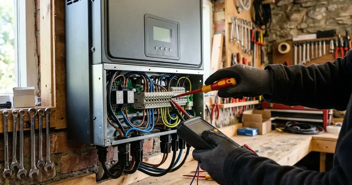
When a Solis solar inverter displays alarm code 1035 (RelayChk-Fail), the inverter's internal safety processor has detected a mechanical or electrical failure in its grid disconnect relays. In accordance with Irish grid connection rules under NSAI I.S. EN 50549-1 and ESB Networks standards, every grid-tied inverter contains internal electromechanical relays that serve as the primary automatic disconnection switch.
Before synchronizing solar generation with the domestic distribution board, the inverter carries out a self-diagnostic routine. It measures voltage across the relay contacts in both open and closed states to confirm that the contacts are functioning correctly and will disengage instantaneously during an islanding event or grid outage. When this test fails, generation is inhibited immediately.
1. Relay Failure Mechanics & Initial Triage
The underlying cause of a 1035 alarm depends on whether the system is newly installed or has operated normally for several years:
- Mechanical Relay Sticking: Due to the working of the relay continuously the relay would have got struck due to which the fault occurs. High switching duty cycles, thermal expansion, or continuous arcing during grid fluctuations can cause internal relay contacts to pit, weld, or physically seize.
- 30-Minute Controlled Discharge: In many instances, a transient software glitch or contactor hesitation can be cleared by discharging the unit. Discharge inverter for 30min. If the inverter backs to work normally, then let it go.
[!WARNING]High-voltage DC strings from rooftop modules remain energized whenever daylight is present, and internal capacitors retain lethal voltages after shutdown. Always turn off the external AC circuit breaker first, open the DC rotary isolator second, and wait at least 15 minutes before touching any wiring or opening terminal enclosures.
To carry out the discharge procedure, completely isolate both the AC and DC supplies. Allow the inverter to remain de-energized for 30 minutes so internal electrolytic capacitors bleed down completely. Re-energize the DC isolator first, followed by the AC supply, and observe whether the startup self-test clears the 1035 code.
2. AC Connection & Gland Polarity Verification
If the 1035 code appears on a newly installed inverter, mechanical relay failure is unlikely. The issue is usually caused by incorrect external wiring:
- AC Gland Wiring: If installation is new then please check connectivity is proper or not of AC gland make sure AC cable connect properly in connector terminal only. (The polarity is clearly mentioned on AC gland). Crossing line and neutral conductors causes the internal sensing circuits to read unexpected phase potentials during relay testing.
- Terminal Screw Torque: Please check all the wire connections from AC connectors to the AC distribution box and in meter side/LT panel/ Transformer side also (were there any untighten connections, or wire contact area is too small). Loose connections introduce localized resistance and voltage drops that distort pre-commissioning checks.
- Remediating Loose Terminations: If suspecting loose contact please properly connect the cable after disconnect from connector, ACDB, Meter /Grid source. Re-seat conductors and re-torque screws to manufacturer specifications.
- Protective Earthing Verification: Check earthing cable size and connectivity should be proper. Under Safe Electric regulations, a high-integrity protective earth conductor must connect the inverter chassis to the main earthing terminal (MET).
3. Voltage Diagnostics & Ground Fault Delta Testing
To determine whether the issue originates inside the inverter or on the connected electrical installation, qualified electricians must measure voltage across all AC and DC circuits:
- Three-Phase Grid Verification: If system is three phase (Check AC side voltage Phase to Phase, phase to neutral and neutral to earthing.) Always check reading from inverter AC gland end.
- Single-Phase Grid Verification: If system is single phase (Check AC side voltage Phase to neutral, phase to earthing and neutral to earthing.) Always check reading from inverter AC gland end.
- DC String Open-Circuit Voltage: Please check the VOC of all of the PV strings (Voltage should check from connector end after disconnect string from inverter).
- Insulation Resistance Earth Delta: Use a multi-meter to check the voltages between PV+ and earth, PV- and earth of all the PV strings. It should be decreasing from values between 5% and 95% of single PV module Voc. If voltage remains static or increases, high DC ground leakage is interfering with internal relay testing.
4. Operational Data & Technical Support Escalation
If physical terminations are verified, line voltages comply with Irish standards, and the 30-minute discharge does not clear the 1035 alarm, the internal electromechanical relay is permanently damaged:
- Access the inverter display and navigate through the menus to record critical operational data.
- Take complete reading of information menu like DC1, DC2, DC3, DC4 then VA, VB, VC or VGrid then Status (Error) and Total energy.
- Access the advanced menu and take reading from advance info Alarm messages, version, running messages, warning messages.
- Gather installation records: Take ACDB, DCDB close and clear photo, inverter serial no. which is stick on inverter body and inverter complete installation photo.
- Submit these diagnostics to Solis technical support to initiate a warranty chassis replacement.
5. Safe Electric Regulatory Obligations in Ireland
Because internal grid disconnect relays are safety-critical protective elements governed by Irish microgeneration regulations, homeowners and installers must adhere to national electrical standards:
- Testing and Inspection: The new installation shall be tested in accordance with Chapter 6. Also, see clause 712.6.101 for additional system documentation, commissioning tests and inspection requirements as per I.S. EN 62446.
- Contractor Responsibility: While Safe Electric provides guidance on fixed wiring compliance, the ultimate responsibility lies with the REC to ensure full adherence to I.S. 10101 and safe operation under all conditions.
- Field Repair Prohibition: Installers must never attempt to desolder or bypass internal relays on-site. Any tampering with internal inverter components voids product certification and violates Safe Electric rules. When an inverter is replaced, the REC must test earth loop impedance, verify RCD trip times, and issue a formal Certificate of Completion.
Frequently asked questions
What causes a 1035 RelayChk-Fail alarm on a Solis inverter in Ireland?
The alarm indicates that the inverter pre-commissioning relay self-test detected welded, stuck, or damaged AC grid disconnect relay contacts or loose AC terminal wiring.
Can a homeowner repair a 1035 RelayChk-Fail error themselves?
No. While a 30-minute full AC and DC power cycle can be attempted to clear firmware logic, inspecting internal relays requires a Safe Electric Registered Electrical Contractor.
What standards govern inverter safety disconnect relays in Ireland?
Under NSAI I.S. EN 50549-1 and SEAI guidelines, inverters must feature redundant grid disconnection relays with verified anti-islanding protection settings.
References
- Solis Service Center - 1035 RelayChk-Fail Troubleshooting — accessed 17 September 2026
- Safe Electric Ireland - Solar PV Technical Guidance — accessed 17 September 2026
- SEAI Domestic Solar Photovoltaic Code of Practice — accessed 17 September 2026
Related guides
More from inverter errors & fixes.