Dyness Tower High Voltage Battery And CAN Protocol Guide
Updated 15 September 2026 · By SolarNevs Research Desk, Dealer surveys + verified sources · 3 sources · Method ↗
Key Takeaways
- Always bond the inverter chassis and battery enclosure to the main earthing terminal.
- Ensure AC circuit isolation and lock-out before installing Current Transformer (CT) clamps.
- An MCS Certificate is required for export tariffs and building regulations compliance.
- Specific wiring diagrams and CAN protocol settings are found in manufacturer documentation.
Understanding High-Voltage Battery Stacking and Distribution
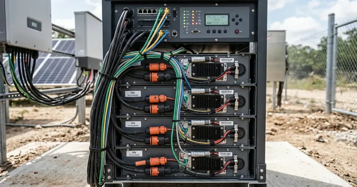
High-voltage battery systems, such as the Dyness Tower series, use multiple battery modules connected in series to achieve a higher system voltage. This approach can improve efficiency and reduce current requirements for a given power output. Stacking refers to the physical and electrical connection of these modules.
A Battery Distribution Unit (BDU) acts as a central interface for these stacked modules. It typically handles the aggregation of power from individual battery modules, provides overall system protection, and facilitates communication with the inverter. The BDU ensures that the battery system operates safely and efficiently.
Inverter Communication via CAN Protocol
The Controller Area Network (CAN) protocol is a robust communication standard widely used in automotive and industrial applications, including energy storage systems. It allows the inverter and the battery management system (BMS) within the battery modules to exchange critical data. This data includes the battery's state of charge, voltage, current, temperature, and fault conditions.
This communication enables the inverter to dynamically manage battery charge and discharge. For example, the "ESS assistant dynamically manages battery charge and discharge based on grid tariffs and load." This intelligent management optimises energy flow, potentially reducing electricity costs and extending battery life. To ensure reliable communication, it is important to "maintain shielded twisted-pair cabling and verify proper RS485 communication baud rate settings."
Essential Safety and Installation Practices
Installing high-voltage battery systems requires strict adherence to safety protocols and electrical standards. One fundamental safety requirement is proper earthing. It is critical to "bond inverter chassis ground and battery metal enclosure to the main installation earthing terminal." This ensures that any fault current is safely directed to the earth, protecting personnel and equipment.
When working with current measurement devices, such as CT clamps, safety is paramount. Always "ensure complete AC circuit isolation and lock-out before installing CT clamps on live busbars." This prevents accidental contact with live circuits. The correct orientation of CT clamps is also vital for accurate system monitoring. "Install Current Transformer clamps with arrows pointing towards the household loads away from the grid incomer." If an inverter reports "negative power flow during high household consumption," it "indicates inverted CT clamp installation."
What You Can Check Yourself, and What You Cannot
As a homeowner, you can perform visual checks and monitor system performance through your inverter's display or app. You can verify that all visible connections appear secure and that the system is operating as expected according to its normal indicators. If you notice "negative power flow during high household consumption," you can check the orientation of your CT clamps, ensuring the arrows point towards the household loads.
Activity / Component | Homeowner Scope (Visual & Monitoring) | Accredited Electrical Engineer Scope |
|---|---|---|
High-Voltage DC Stacking | Visual check of exterior stack alignment | Physical series module inter-wiring and BDU connection |
CAN Bus Communication | Monitoring telemetry on inverter app/display | Pinout configuration, baud rate sync, and shielded pair routing |
CT Clamps | Verifying arrow direction points towards loads | Busbar isolation, lock-out, and live panel termination |
Earthing & Bonding | Visual check of ground cable presence | Bonding chassis and metal enclosure to main earthing terminal |
Commissioning & Safety | Normal system operation verification | Insulation resistance testing, polarity verification, and sign-off |
However, any work involving the physical wiring, internal components of the inverter, or battery modules must be performed by an accredited electrical engineer or certified installer. This includes:
- Connecting or disconnecting high-voltage battery modules.
- Wiring the Battery Distribution Unit (BDU).
- Configuring CAN protocol settings beyond basic user interface options.
- Performing insulation resistance testing or polarity verification.
"All DC conductors, AC feeders, and auxiliary control cables must be installed in compliance with applicable national electrical codes and verified by an accredited electrical engineer." Opening the inverter or battery enclosure can expose you to hazardous voltages and should only be done by authorised service personnel after isolating all power sources and waiting the manual's specified capacitor discharge time.
What the Published Sources Do Not Tell You
The provided source material offers general guidelines on safety, regulatory compliance, and system monitoring applicable to microgeneration and energy storage systems. However, it does not contain specific technical details for the Dyness Tower (HV51100) modular series.
Specifically, the source does not provide:
- Detailed instructions or diagrams for Dyness Tower (HV51100) battery stacking procedures.
- Specific wiring diagrams for the Battery Distribution Unit (BDU) for the Dyness Tower series.
- Exact CAN protocol settings, baud rates, or message structures required for multi-brand inverter compatibility with Dyness Tower batteries.
- Specific fault codes or diagnostic procedures for Dyness Tower batteries or their BDU.
- The exact connection capacity limits or manufacturer equipment ratings for the Dyness Tower series.
For these specific details, you must consult the official Dyness Tower installation manuals, datasheets, and any specific integration guides provided by Dyness or the inverter manufacturer for your particular model combination. "System Architecture & Sizing" and "Wiring & Isolation" are "Sized according to site-specific engineering drawings, local utility connection capacity, and manufacturer equipment ratings." "Complete pre-commissioning checks, insulation resistance testing, and polarity verification prior to final energization and utility permission to operate" are also essential steps not detailed here.
Add a battery at a surveyed price
Installers quote supply and fitting of the battery on this page for your existing or new system.
How this pays for the site: installers pay SolarNevs a fixed introduction fee when we pass them a genuine enquiry. They cannot pay to appear higher, and our surveyed prices are published before any introduction. You can also take our dated price tables straight to any installer.
Frequently asked questions
What are the primary technical requirements for dyness tower high voltage battery and can protocol guide?
Key requirements include compliance with local grid codes, correct equipment certification, and proper electrical isolation.
Who is authorized to install and inspect dyness tower high voltage battery and can protocol guide?
All high-voltage DC, AC grid tie-in, and switchboard modifications must be performed by a qualified, accredited electrical professional.
How is export power limited in dyness tower high voltage battery and can protocol guide?
Export limiting is achieved using certified bidirectional smart meters or power sensors providing dynamic feedback to the inverter system.
References
- Dyness Tower high-voltage home storage battery: model range, stackable module counts and parallel limits — accessed 6 September 2026
- Dyness inverter matching list — downloadable Tower series inverter compatibility lists for multi-brand integration — accessed 6 September 2026
- NEPRA (Prosumer) Regulations, 2026 (S.R.O. 251(I)/2026) — interconnection, metering and protection apparatus, and licensee inspection before parallel operation — accessed 6 September 2026
Related guides
More from what to buy — and how not to get cheated.