Victron Battery Balancer: 24V and 48V Active Balancing Guide
Updated 6 September 2026 · By SolarNevs Research Desk, Dealer surveys + verified sources · 2 sources · Method ↗
Key Takeaways
- Battery imbalance is a primary cause of premature battery bank failure in series-connected systems.
- Check for midpoint voltage deviation using the balancer's LEDs or a multimeter as a first diagnostic step.
- Always isolate the battery bank and use insulated tools before handling connections to prevent dangerous high-current short circuits.
- If the alarm persists after verifying connections and battery health, or if batteries are mismatched, consult a qualified technician.
Why do batteries in a series bank become unbalanced?
The service life of an expensive battery bank can be substantially shortened due to state of charge unbalance. Even small differences in internal resistance or self-discharge rates between series-connected 12V batteries can lead to one battery being consistently overcharged and another undercharged. This imbalance causes premature sulfation in undercharged blocks and destructive gassing in overcharged blocks, leading to reduced capacity and early failure of the entire bank. The Victron Battery Balancer addresses this by actively equalizing the state of charge.
Diagnosing Battery Imbalance with the Victron Battery Balancer
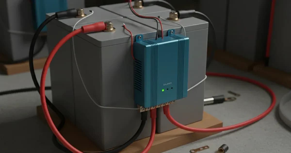
The Victron Battery Balancer continuously monitors the voltage of series-connected 12V batteries and indicates their state of balance through its LED indicators.
- Check Balancer Status LEDs:
- Green LED (On): Indicates the balancer is active because the total battery voltage is above 27.3V (±1%).
- Orange LED (Lower leg active > 0.1V): Shows the balancer is drawing current from the lower 12V battery to balance it with the upper one.
- Orange LED (Upper leg active > 0.1V): Shows the balancer is drawing current from the upper 12V battery to balance it with the lower one.
- Red LED (Alarm Active): This indicates a significant imbalance. The midpoint voltage deviation between series 12V blocks has exceeded 200 mV (0.2V). This also closes the integrated alarm relay.
- Monitor Alarm Relay:
- The balancer includes a 60V / 1A normally open alarm relay. When the Red LED is active (deviation > 200 mV), this relay closes. You can connect an external alarm buzzer or a remote monitoring system like a Victron Cerbo GX digital input to these contacts for remote telemetry.
- The alarm will reset and the Red LED will turn off when the deviation drops below 140 mV (0.14V).
- Check for Low Voltage Standby:
- If the total battery voltage drops below 26.6V (±1%), the balancer deactivates to reduce idle current draw to 0.7 mA. This is normal operation and not an imbalance fault.
Common Causes and Fixes for Battery Imbalance
Symptom detail | Likely cause | Fix |
|---|---|---|
Red LED alarm active (deviation > 200 mV) | Mismatched battery capacities or mixing aged and new batteries. | Ensure all series-connected 12V batteries are of the same brand, model, age, and capacity. Replace mismatched batteries. |
Red LED alarm active (deviation > 200 mV) | Incorrect or missing midpoint interconnect wiring. | Verify all wiring connections, especially the midpoint connection, for correct polarity and secure terminals. Refer to the wiring diagrams in the manual. |
Red LED alarm active (deviation > 200 mV) in 48V system | Failure to install three separate balancers. | For a 48V battery bank, install three Battery Balancers: one for each 24V series pair, and one between the midpoints of the two 24V banks. |
Balancer not active, no LEDs on | Total battery voltage below 27.3V (±1%). | This is normal operation. The balancer activates only when the total charging voltage exceeds 27.3V (±1%). |
Balancer not active, no LEDs on | Balancer is in low voltage standby. | The balancer deactivates if the total battery voltage drops below 26.6V (±1%) to minimize idle current draw. This is normal. |
Setup and Operation of the Victron Battery Balancer
The Victron Battery Balancer is designed for straightforward installation and automatic operation. It equalizes the state of charge of two series-connected 12V batteries. For larger systems, multiple balancers are used.
Wiring for 24V Systems
For a 24V battery bank consisting of two series-connected 12V batteries:
- Connect the Battery Balancer's negative terminal to battery minus (0V).
- Connect the balancer's middle terminal to the series midpoint (+12V) between the two batteries.
- Connect the balancer's positive terminal to battery plus (+24V).
Wiring for 48V Systems
For a 48V battery bank, which typically consists of four series-connected 12V batteries (forming two 24V pairs):
- You will need three Victron Battery Balancers.
- Balancer 1: Connect across the first 24V series pair (Battery 1 and Battery 2).
- Balancer 2: Connect across the second 24V series pair (Battery 3 and Battery 4).
- Balancer 3: Connect between the midpoints of the two 24V banks. This ensures balancing across the entire 48V string.
Operational Thresholds
The balancer operates automatically based on voltage thresholds:
- Input Voltage Range: The balancer can handle up to 18V per battery, with a total DC input of 36V.
- Turn-On Threshold: The balancer activates when the total charging voltage exceeds 27.3V (±1%).
- Turn-Off Threshold: It deactivates when the total battery voltage drops below 26.6V (±1%).
- Idle Current Draw: When off, the balancer draws a minimal 0.7 mA.
- Balancing Start Deviation: Balancing begins when the midpoint voltage deviation between series 12V batteries reaches 50 mV (0.05V).
- Maximum Active Balancing Current: The balancer can transfer a maximum of 0.7A when the midpoint voltage deviation is greater than 100 mV.
- Alarm Trigger Level: A Red LED illuminates and the alarm relay closes if the deviation reaches 200 mV (0.2V).
- Alarm Reset Level: The Red LED turns off and the alarm relay opens when the deviation drops below 140 mV (0.14V).
External Alarm and Reset
The balancer features two dedicated terminals for an external momentary push button. Interconnecting these two terminals will reset the alarm relay. You can also connect an external alarm buzzer or a remote monitoring system to the 60V / 1A normally open alarm relay contacts.
For more detailed system integration, especially with other Victron components, you may refer to guides on the Victron SmartShunt and Lynx Distributor wiring or the Victron Cerbo GX CANbus energy storage synchronization guide.
Safety: Handling Battery Balancer Installations
Working with battery banks involves significant electrical hazards. Always prioritize safety.
- Isolate the Battery Bank: Before connecting or disconnecting any terminals, isolate the entire battery bank by disconnecting all charging sources (solar, grid, generator) and loads.
- Install Fuses: Install inline fuses on all balancer sensing leads as close to the battery terminals as possible. This protects against short circuits.
- Use Insulated Tools: Always use insulated tools when working on battery connections. A spanner across a battery bank can cause a dangerous high-current short circuit, leading to severe burns or explosions.
- Avoid Metal Contact: Never place metal tools or jewelry across battery posts.
- Matching Batteries: Ensure all series-connected 12V batteries are of the same brand, model, age, and capacity. Mixing different battery types or ages can lead to persistent imbalance and reduce the effectiveness of the balancer.
When to call a technician instead
While the Victron Battery Balancer is designed for automatic operation, persistent issues or complex installations may require professional assistance.
Call a qualified solar or battery technician if:
- The Red LED alarm remains active despite verifying all connections and ensuring batteries are matched.
- You are unsure about the correct wiring for a 48V system or a complex series-parallel configuration.
- You suspect internal battery damage or failure, which the balancer cannot fix.
- You need to integrate the balancer with advanced monitoring systems and are unfamiliar with the process.
Attempting to troubleshoot complex electrical issues without proper knowledge and tools can be dangerous and may void your battery or balancer warranty. Victron Energy offers a 5-year standard warranty and global repair service for their products.
Add a battery at a surveyed price
Installers quote supply and fitting of the battery on this page for your existing or new system.
How this pays for the site: installers pay SolarNevs a fixed introduction fee when we pass them a genuine enquiry. They cannot pay to appear higher, and our surveyed prices are published before any introduction. You can also take our dated price tables straight to any installer.
Frequently asked questions
What does the Victron Battery Balancer do?
It equalizes the state of charge of two series-connected 12V batteries in a 24V bank, or up to three balancers across series-parallel strings in a 48V bank. This prevents capacity degradation and premature failure due to imbalance.
At what voltage does the Victron Battery Balancer activate?
The balancer activates automatically when the total charging voltage exceeds 27.3V (±1%). It dynamically transfers up to 0.7A balancing current from higher to lower voltage batteries.
How many balancers are needed for a 48V system?
A 48V battery bank requires three Victron Battery Balancers. One balancer is used for each 24V series pair, and a third balancer is connected between the midpoints of the two 24V banks.
What does the red LED on the balancer indicate?
A red LED indicates that the midpoint voltage deviation between series 12V blocks has exceeded 200 mV (0.2V). This also closes the integrated alarm relay.
What is the maximum balancing current?
The Victron Battery Balancer can transfer a maximum active balancing current of 0.7A when the midpoint voltage deviation is greater than 100 mV.
References
- Victron Energy Battery Balancer Manual — accessed 23 August 2026
- Victron Energy Battery Balancer Product Page — accessed 23 August 2026
Related guides
More from what to buy — and how not to get cheated.