Victron Digital Multi Control GX: Setup Guide
Updated 16 September 2026 · By SolarNevs Research Desk, Dealer surveys + verified sources · 1 source · Method ↗
Key Takeaways
- The Digital Multi Control GX provides simple, robust remote management for MultiPlus and Quattro inverter/charger systems.
- System architecture support: The Digital Multi Control 200/200A GX enables remote monitoring and control of inverter/charger systems in stand-alone, parallel, and 2- or 3-phase configurations..
- Master power control: The switch can be used to turn the inverter/charger system on, off or to charger-only mode..
- Comprehensive visual feedback: Eight LEDs replicate the inverter/charger LEDs..
- Real-time numerical readout: The 7-segment display primarily shows the AC input current.
- Dynamic current throttling: The control panel's knob adjusts the AC input current limit..
- Multi-unit scaling parameter: Scaling factor 0 0 - 9.
- Auxiliary generator threshold: Generator current (A) 16 0 - 198.
- Primary AC shore limit: Upper AC current limit for AC1 input (A) 254 0 - 254.
- Secondary AC generator limit: Upper AC current limit for AC2 input (A) 254 0 - 254.
- Standard communication link: Use an RJ45 UTP cable to connect the control panel to the inverter/charger..
VE.Bus Panel Architecture & Rotary Shore Throttling
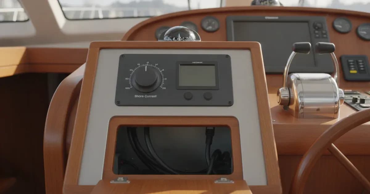
The Digital Multi Control GX allows operators to quickly dial down the AC input current limit when plugging into weak marina shore power pedestals, camping posts, or portable generators, preventing nuisance shore breaker trips by triggering MultiPlus PowerAssist.
The Victron Digital Multi Control GX is a remote inverter/charger control panel for MultiPlus and Quattro systems, featuring a rotary current limit dial, 7-segment LED display, and 8 system status LEDs:
- Power Mode Switch: ON / OFF / Charger, 8 Replicated LEDs, Auto Dimming LEDs, Standalone/Parallel.
- Rotary Current Knob: Sets AC Shore In, Prevents Tripping, Dynamic Control, 7-Segment AC Read.
- Configuration: Scale 0 - 9, Gen 0 - 198A, AC1 0 - 254A, RJ45 VE.Bus.
Installation Sequence & VE.Bus Interconnection
- Panel Mounting: Cut the flush-mount opening in the monitoring dashboard or power locker.
- VE.Bus Cable Routing: Use an RJ45 UTP cable to connect the control panel to the inverter/charger. into any vacant VE.Bus port.
- System Power Verification: Toggle The switch can be used to turn the inverter/charger system on, off or to charger-only mode. to verify communication.
Setup Menu Parameters & Multi-Inverter Scaling
The rear push-button enters the on-board configuration menu to customize system parameters:
- Multi-Unit Systems: When multiple inverters operate in parallel, set Scaling factor 0 0 - 9 to properly scale the rotary dial current adjustment across all units.
- Generator Current Limits: Program the dedicated threshold at Generator current (A) 16 0 - 198 to match genset continuous ratings.
- Dual AC Inputs: Configure individual upper boundaries across Upper AC current limit for AC1 input (A) 254 0 - 254 and Upper AC current limit for AC2 input (A) 254 0 - 254.
- Status Telemetry: Live operating status is verified as Eight LEDs replicate the inverter/charger LEDs. and The 7-segment display primarily shows the AC input current while The control panel's knob adjusts the AC input current limit..
- Broad System Scope: Fully supported because **The Digital Multi Control 200/200A GX enables remote monitoring and control of inverter/charger systems in stand-alone, parallel, and 2- or 3-phase configurations.**.
Technical Specifications & Sizing Summary
Parameter | Engineering Rating | Design Significance |
|---|---|---|
System Architecture Support | The Digital Multi Control 200/200A GX enables remote monitoring and control of inverter/charger systems in stand-alone, parallel, and 2- or 3-phase configurations. | Universal compatibility across all VE.Bus systems |
Power Control Switch | The switch can be used to turn the inverter/charger system on, off or to charger-only mode. | Physical 3-position mode selector |
Status LED Indicators | Eight LEDs replicate the inverter/charger LEDs. | Direct visual replication of MultiPlus/Quattro status |
Numerical Display | The 7-segment display primarily shows the AC input current | High-visibility digital readout of live AC current |
Rotary Current Dial | The control panel's knob adjusts the AC input current limit. | Ergonomic real-time adjustment of shore current |
Scaling Factor Range | Scaling factor 0 0 - 9 | Matches rotary dial span to paralleled inverter counts |
Generator Current Range | Generator current (A) 16 0 - 198 | Dedicated current ceiling when generator input is active |
AC1 Input Current Range | Upper AC current limit for AC1 input (A) 254 0 - 254 | Upper limit for primary shore power connection |
AC2 Input Current Range | Upper AC current limit for AC2 input (A) 254 0 - 254 | Upper limit for secondary AC generator connection |
Network Cabling | Use an RJ45 UTP cable to connect the control panel to the inverter/charger. | Standard plug-and-play VE.Bus communication link |
Add a battery at a surveyed price
Installers quote supply and fitting of the battery on this page for your existing or new system.
How this pays for the site: installers pay SolarNevs a fixed introduction fee when we pass them a genuine enquiry. They cannot pay to appear higher, and our surveyed prices are published before any introduction. You can also take our dated price tables straight to any installer.
Frequently asked questions
What inverter/charger architectures and power modes are controlled by the DMC GX?
**The Digital Multi Control 200/200A GX enables remote monitoring and control of inverter/charger systems in stand-alone, parallel, and 2- or 3-phase configurations.** where **The switch can be used to turn the inverter/charger system on, off or to charger-only mode.** (August 2026).
What visual telemetry and current limit adjustment controls are built in?
**Eight LEDs replicate the inverter/charger LEDs.** while **The 7-segment display primarily shows the AC input current** as **The control panel's knob adjusts the AC input current limit.** (August 2026).
What configuration menu parameters and system cabling apply?
Configuration sets **Scaling factor 0 0 - 9**, **Generator current (A) 16 0 - 198**, **Upper AC current limit for AC1 input (A) 254 0 - 254**, and **Upper AC current limit for AC2 input (A) 254 0 - 254** using **Use an RJ45 UTP cable to connect the control panel to the inverter/charger.** (August 2026).
References
- Victron Energy: Digital Multi Control Manual — accessed 31 August 2026
Related guides
More from what to buy — and how not to get cheated.