Victron Lynx Shunt VE.CAN: Battery Monitor Setup
Updated 16 September 2026 · By SolarNevs Research Desk, Dealer surveys + verified sources · 1 source · Method ↗
Key Takeaways
- The Lynx Shunt VE.Can serves as the central battery monitor and primary system fuse holder in modular Lynx DC distribution systems.
- Supports heavy commercial DC currents: Current rating 1000 Adc continuous through solid Busbar dimensions (hxw) 8 x 30mm tinned copper busbars.
- Handles multiple nominal voltages: Supported system voltages 12, 24 or 48 V with a wide Supply voltage range 9 - 70 Vdc.
- Minimal quiescent current drain: Power consumption 60 mA @ 12 V 33 mA @ 24 V 20 mA @ 48 V.
- Standardized modular busbar interconnects: Busbar M10 connecting bolts.
- Accommodates main system protection: Fuse or fuse dummy M8 (a Mega fuse can be installed on the M6 bolts).
- High-speed digital networking: VE.Can RJ45 and RJ45 terminator ports communicating directly with GX devices.
- Includes dry-contact fault automation: Potential free alarm contact 3 A, 30 Vdc, 250 Vac.
- Built for rugged battery compartments: Unit weight 1.4 kg and Enclosure dimensions (hxwxd) 190 x 180 x 80mm.
- Resilient environmental ratings: Protection class IP22 operating from Operating temperature range -40 °C to +60 °C.
Modular Busbar Architecture & Current Measurement
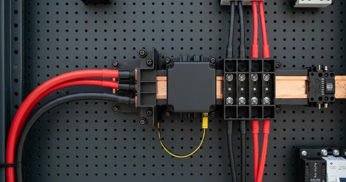
The Lynx Shunt VE.Can is designed to sit directly between battery banks (connected via Lynx Power In) and DC loads/chargers (connected via Lynx Distributor). Its internal resistive shunt measures every ampere flowing into and out of the battery bank with laboratory precision.
The Victron Lynx Shunt VE.Can serves as a 1000 Adc modular battery monitor and main DC fuse holder across a 9 - 70 Vdc operating range for 12V, 24V, and 48V battery banks. It provides:
- DC Power & Shunt: 1000A Continuous, 8x30mm Copper Bars, M10 Interconnects, Low Power Draw.
- Fusing & Alarms: M8 Center Studs, M6 Mega Option, 3A Alarm Relay, Temp Sensor Port.
- Comms & Power: Dual VE.Can, RJ45 TermPlug, RJ10 PowerOut, NMEA2000 Data.
Installation Rules & Mechanical Assembly
- Modular Bolting: Interconnect the Lynx Shunt VE.Can to adjacent Lynx modules using the supplied Busbar M10 bolts, torquing to 33 Nm on the Busbar dimensions (hxw) 8 x 30mm tinned copper conductors.
- Main Fuse Placement: Install an appropriately rated CNN or ANL fuse on the center Fuse or fuse dummy M8 (a Mega fuse can be installed on the M6 bolts) studs, torquing to 14 Nm.
- Wide System Voltage: Compatible with Supported system voltages 12, 24 or 48 V across a Supply voltage range 9 - 70 Vdc.
VE.Can Network Integration & Hardware Automation
The Lynx Shunt VE.Can provides full system telemetry to Cerbo GX and VRM portals:
- High-Speed VE.Can Bus: Connecting dual VE.Can RJ45 and RJ45 terminator sockets at 250 kbps allows GX system controllers to calculate accurate State of Charge (SoC), time-to-go, and consumed ampere-hours.
- Low Quiescent Draw: Maintains active telemetry with negligible standby loss: Power consumption 60 mA @ 12 V 33 mA @ 24 V 20 mA @ 48 V.
- Potential-Free Alarm Relay: The internal Potential free alarm contact 3 A, 30 Vdc, 250 Vac trips automatically on low SoC, high/low voltage, or blown main fuse events.
- Lynx Distributor Power: An onboard RJ10 socket provides power and blown-fuse detection logic to downstream Lynx Distributor modules.
- Rugged Housing: Encased in an ABS enclosure with Protection class IP22, Enclosure dimensions (hxwxd) 190 x 180 x 80mm, Unit weight 1.4 kg, and an Operating temperature range -40 °C to +60 °C.
Technical Specifications & Connection Summary
Parameter | Engineering Rating | Design Significance |
|---|---|---|
Continuous DC Current | Current rating 1000 Adc continuous | Sized for large multi-inverter battery systems |
Supply Operating Range | Supply voltage range 9 - 70 Vdc | Universal operation from 12V up to 48V nominal banks |
System Bank Compatibility | Supported system voltages 12, 24 or 48 V | Auto-detected or manually configured in GX settings |
Standby Current (12V) | Power consumption 60 mA @ 12 V | Low parasitic draw on 12V starter/house banks |
Standby Current (24V) | Power consumption 33 mA @ 24 V | Efficient monitoring on 24V marine systems |
Standby Current (48V) | Power consumption 20 mA @ 48 V | Ultra-low draw on residential and commercial storage |
Main Fuse Mounting | Fuse or fuse dummy M8 (a Mega fuse can be installed on the M6 bolts) | Accommodates standard high-current CNN/ANL fuses |
Modular Busbar Terminals | Busbar M10 | Heavy-duty bolted connection to adjacent Lynx blocks |
Busbar Cross-Section | Busbar dimensions (hxw) 8 x 30mm | Solid tinned copper conductor minimizes voltage drops |
Network Interface | VE.Can RJ45 and RJ45 terminator | Galvanically isolated CAN bus communication |
Dry Alarm Relay | Potential free alarm contact 3 A, 30 Vdc, 250 Vac | Hardware-level signaling to buzzers or safety trip coils |
Mechanical Footprint | Unit weight 1.4 kg (190 x 180 x 80mm) | Standardized Lynx modular form factor |
Environmental Limits | Protection class IP22 (-40 °C to +60 °C) | Resilient thermal and ingress performance |
Add a battery at a surveyed price
Installers quote supply and fitting of the battery on this page for your existing or new system.
How this pays for the site: installers pay SolarNevs a fixed introduction fee when we pass them a genuine enquiry. They cannot pay to appear higher, and our surveyed prices are published before any introduction. You can also take our dated price tables straight to any installer.
Frequently asked questions
What supply voltages and continuous current capacity are supported by the Lynx Shunt VE.Can?
The unit operates across a **Supply voltage range 9 - 70 Vdc** with **Supported system voltages 12, 24 or 48 V** and delivers a **Current rating 1000 Adc continuous** (August 2026).
What is the quiescent power consumption across 12V, 24V, and 48V systems?
It draws **Power consumption 60 mA @ 12 V 33 mA @ 24 V 20 mA @ 48 V** (August 2026).
What hardware connections are provided for the busbars, main fuse, and networking?
It features a **Busbar M10**, center **Fuse or fuse dummy M8 (a Mega fuse can be installed on the M6 bolts)**, **VE.Can RJ45 and RJ45 terminator**, and solid **Busbar dimensions (hxw) 8 x 30mm** (August 2026).
What are the alarm relay ratings and physical enclosure specifications?
It integrates a **Potential free alarm contact 3 A, 30 Vdc, 250 Vac**, weighs **Unit weight 1.4 kg**, measures **Enclosure dimensions (hxwxd) 190 x 180 x 80mm**, has **Protection class IP22**, and operates across **Operating temperature range -40 °C to +60 °C** (August 2026).
References
- Victron Energy: Lynx Shunt VE.Can Manual — accessed 31 August 2026
Related guides
More from what to buy — and how not to get cheated.