Victron EM330 and EM340 Energy Meter RS485 Setup Guide
Updated 6 September 2026 · By SolarNevs Research Desk, Dealer surveys + verified sources · 1 source · Method ↗
Key Takeaways
- Incorrect RS485 wiring polarity (A/B swapped) is the most common cause of communication issues.
- Always verify RS485 A/B connections and ensure the main AC supply is de-energized before installation.
- Never open-circuit the secondary terminals of external current transformers (CTs) on the EM330 while primary current is flowing.
- If complex AC wiring is involved or you are uncomfortable with electrical work, stop and consult a qualified technician.
How do I set up Victron EM330 and EM340 energy meters for RS485 communication?
Setting up Victron EM330 and EM340 energy meters involves correct physical wiring and configuration within the Victron Venus OS. These meters communicate with a Victron GX device, such as a Cerbo GX, via RS485 Modbus RTU. The most frequent setup problem is incorrect RS485 A/B wiring polarity, which prevents communication.
Diagnosis
Follow these steps to diagnose setup and communication issues with your Victron EM330 or EM340 energy meter:
- Check Physical Connections:
- RS485 Wiring: Ensure the RS485 A and B data lines are correctly connected between the energy meter and the Victron RS485 to USB interface cable or Zigbee converter. Swapping A and B polarity will prevent communication.
- AC Voltage Leads: Verify that the AC voltage leads are securely terminated and the meter is receiving power. The front-panel LCD display should be active.
- CT Wiring (EM330 only): For the EM330, ensure external current transformers are correctly oriented and their secondary leads are securely connected to the meter. Incorrect orientation can lead to negative power readings.
- Verify Venus OS Configuration:
- Meter Role: On your Victron GX device, navigate to the device list and select the connected energy meter. Confirm that its role is correctly configured as "Grid Meter," "PV Inverter," "Generator," or "AC Load" as appropriate for your system.
- Communication Status: Check the communication status of the energy meter within Venus OS. A "Grid Meter Lost" warning indicates a communication timeout.
- Observe Meter Display:
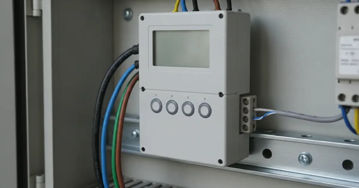
- LCD Display: The EM330 and EM340 meters feature a front-panel backlit LCD display. Confirm it is powered on and showing readings. This indicates the meter itself is receiving AC power.
- Check for Specific Alarms:
- "Grid Meter Lost" Warning: If this warning appears on your GX device, it means RS485 polling has failed or wiring latency exceeds timeout limits. This will cause the ESS inverter to switch into safe passthrough mode.
- "Inverted CT Polarity Alert" (EM330): If you observe negative power calculations on a specific phase for an EM330, it suggests the secondary current transformer leads for that phase are reversed. This can lead to improper charging or discharging in an ESS.
Cause/fix table section
Symptom detail | Likely cause | Fix |
|---|---|---|
No communication with GX device, meter not appearing in Venus OS | RS485 A/B data polarity swapped | Reverse the RS485 A and B wires at either the meter or the RS485-to-USB adapter. |
"Grid Meter Lost" warning on GX device | RS485 communication timeout or excessive latency | Check all RS485 wiring for secure connections. Ensure the total cable length is within limits. The GX polling latency at 9600 baud is typically between 180ms and 250ms. |
Negative power readings on one or more phases (EM330 only) | Inverted CT polarity on specific phase(s) | Reverse the secondary current transformer leads for the affected phase(s) at the EM330 terminal block. |
EM340 meter failure or damage | Exceeding the 65A per phase continuous direct current limit | The EM340 is designed for direct measurement up to 65A per phase. If your system exceeds this, use an EM330 with external CTs. The internal shunts of the EM340 can be thermally destroyed by overcurrent. |
High voltage spikes during EM330 installation/maintenance | Disconnecting CT secondary leads under primary load without shorting blocks | Always short the secondary terminals of external current transformers before disconnecting them, especially when primary current is flowing. This prevents dangerous high voltage induction. |
Communication and Configuration
The Victron EM330 and EM340 energy meters are integral for accurate energy monitoring in Victron ESS (Energy Storage System) and PV installations. They utilize the RS485 Modbus RTU protocol for communication with Victron GX devices.
Communication Protocol and Wiring
Both the EM330 (Part Number: REL300300000 / EM330DINAV53HS1X) and EM340 (Part Number: REL300100000 / EM340DINAV23XS1X) communicate via RS485 Modbus RTU. This connection can be established in two ways:
- Wired Connection: Using a Victron RS485 to USB interface cable (available in 1.8m or 5.0m lengths) directly to a USB port on your GX device (e.g., Cerbo GX).
- Wireless Connection: Via Zigbee converters (Zigbee to USB and Zigbee to RS485) for installations where wired runs are impractical.
The meters feature a 1000ms register update rate. The GX device polling latency, when communicating at 9600 baud, is typically between 180ms and 250ms.
Meter Functionality and Models
These meters are designed for three-phase AC installations, though they can support single-phase measurement. They provide active power factor reporting and use vector energy registration.
- EM340 (REL300100000 / EM340DINAV23XS1X): This model offers three-phase direct measurement up to 65A per phase. It is suitable for systems where the continuous current per phase does not exceed this limit.
- EM330 (REL300300000 / EM330DINAV53HS1X): For three-phase systems exceeding 65A per phase, the EM330 is used in conjunction with external current transformers (CTs). It accepts a 5A per phase secondary CT input.
Venus OS Configuration
Once physically connected, the meter's role must be configured in Venus OS on your GX device. The energy meters can be configured as a "Grid Meter" in an ESS installation, to measure the output of a "PV Inverter," a "AC Genset," or as an "AC Load" monitor. This configuration determines how the GX device interprets the meter's data within the overall system.
For more detailed wiring guidance on other Victron components, you can refer to our guides on Victron SmartShunt and Lynx Distributor Wiring or Victron Lynx Distributor and Modular DC Busbar Wiring Guide. If you are working with DC-DC charging solutions, our Victron Orion-Tr Smart DC-DC Charger and Dual Battery Setup Guide might also be helpful.
Safety
Working with AC electrical systems and current transformers requires strict adherence to safety protocols.
- De-energize AC Supply: Always de-energize and lock out the main AC supply breakers before installing the meter or terminating any voltage leads. This prevents electric shock.
- Current Transformer Safety (EM330): Never open-circuit the secondary terminals of external current transformers while primary current is flowing. Doing so can induce dangerously high voltage spikes across the open terminals, posing a severe shock hazard and potentially damaging equipment. If you need to disconnect CT secondary wiring, ensure the primary circuit is de-energized or the CT secondary leads are shorted first.
- Wiring Practices: Connect CT secondary wiring using properly insulated twisted-pair cabling to minimize inductive electrical noise and ensure signal integrity. Use insulated tools when working with electrical connections.
When to call a technician instead
While many setup tasks can be performed by a competent DIYer, there are situations where professional assistance is recommended:
- Complex AC Wiring: If the AC distribution panel or wiring is complex, or if you are unsure about proper wiring practices for high-voltage AC circuits, a qualified electrician should perform the installation.
- Persistent Communication Issues: If, after following all troubleshooting steps, the meter still fails to communicate with the GX device, there may be an internal fault with the meter or the GX device.
- Suspected Internal Damage: If you suspect the meter has been damaged (e.g., due to overcurrent on an EM340 or voltage spikes on an EM330), it should be replaced by a professional.
- Safety Concerns: If you are uncomfortable performing any of the installation or troubleshooting steps, especially those involving live AC circuits, do not proceed. Your safety is paramount.
Add a battery at a surveyed price
Installers quote supply and fitting of the battery on this page for your existing or new system.
How this pays for the site: installers pay SolarNevs a fixed introduction fee when we pass them a genuine enquiry. They cannot pay to appear higher, and our surveyed prices are published before any introduction. You can also take our dated price tables straight to any installer.
Frequently asked questions
What are the main differences between the Victron EM330 and EM340 energy meters?
The EM330 uses external 5A secondary current transformers (CTs) for three-phase systems exceeding 65A per phase. The EM340 provides three-phase direct measurement up to 65A per phase using internal shunts.
How do Victron EM330 and EM340 meters communicate with a GX device?
Both meters communicate via RS485 Modbus RTU to Victron GX devices, such as the Cerbo GX. This can be done through wired RS485-to-USB interface cables or wirelessly via Zigbee converters.
What are the current measurement capabilities of the EM330 and EM340?
The EM330 is designed for systems exceeding 65A per phase, using external CTs with a 5A secondary rating. The EM340 directly measures up to 65A per phase.
What should I do if my Victron GX device shows a 'Grid Meter Lost' warning?
A 'Grid Meter Lost' warning indicates RS485 communication failure or excessive wiring latency. Check your RS485 wiring for correct A/B polarity and secure connections. Ensure the GX device polling latency is within expected limits (180ms to 250ms at 9600 baud).
What safety precautions are necessary when installing these energy meters?
Always de-energize and lock out the main AC supply breakers before installation. Never open-circuit the secondary terminals of external current transformers while primary current is flowing, as this can induce high voltage spikes. Use properly insulated twisted-pair cabling for CT secondary wiring.
References
- Datasheet-Energy-Meters-selection-guide-EN.pdf — accessed 23 August 2026
Related guides
More from what to buy — and how not to get cheated.