Victron EM530 Energy Meter RS485 and CT Setup Guide
Updated 6 September 2026 · By SolarNevs Research Desk, Dealer surveys + verified sources · 1 source · Method ↗
Key Takeaways
- The Victron EM530 (Part number: EM530DINAV53XS1X) uses external 5A secondary current transformers (CTs) for systems exceeding 65A per phase.
- Communication to Victron GX devices occurs via RS485 Modbus RTU, requiring specific wiring and termination.
- Always de-energize the main AC supply and lock out breakers before beginning any installation work.
- Never open-circuit CT secondary terminals while primary conductors carry current, as this can generate dangerously high voltages.
How to Set Up the Victron EM530 Energy Meter
Setting up the Victron EM530 Energy Meter involves correct physical wiring of current transformers (CTs) and RS485 communication, followed by configuration within your Victron GX device. The EM530 is designed for 3-phase AC installations requiring measurement beyond 65A per phase. It functions as a grid meter, PV inverter meter, generator meter, or AC load meter in a Victron Energy Storage System (ESS).
Installation and Wiring Steps
Follow these steps to install and wire your Victron EM530 Energy Meter.
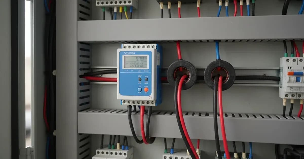
- Safety Preparation:Before starting any electrical work, always de-energize and lock out main AC supply breakers. Verify that all circuits are de-energized using a suitable voltage tester. This prevents electric shock and damage to equipment. 2.Mount the EM530:Mount the EM530DINAV53XS1X energy meter onto a standard DIN rail within your distribution board. Ensure it is securely fastened and has adequate ventilation. 3.Wire Voltage Sense Leads:Connect the voltage sense leads from the main AC supply to the EM530's voltage terminals. The EM530 is compatible with 3-phase AC installations. Use appropriately rated insulated tools for all connections. 4.Connect Current Transformers (CTs):The EM530 uses external CTs for current measurement. Connect the primary conductors (the main AC lines) through the CTs. Then, connect the secondary wires of each CT to the corresponding current input terminals on the EM530. Ensure CT polarity is correct; if CT polarity is reversed on any phase, vector registration computes negative grid power, leading to improper ESS battery discharge into the grid.WARNING: Ensure external CT secondary circuits are securely connected and never open-circuited while primary conductors carry current. Open-circuiting a CT under load can generate extremely high voltages and cause severe injury or equipment damage.
- **Connect RS485 Communication:Connect the EM530 to your Victron GX device (such as a Cerbo GX) using an RS485-to-USB interface cable (available in 1.8m or 5.0m lengths from Victron). Connect the RS485 differential data terminals (A and B) on the EM530 to the corresponding data terminals on the RS485-to-USB adapter. Plug the USB end of the adapter into an available USB port on your GX device. For long cable runs, or if experiencing communication issues, install 120-ohm end-of-line termination resistors at both ends of the RS485 bus. 6.Configure on Victron GX Device:Once physically connected, power on your Victron system. Access the Venus OS interface on your GX device. Navigate to the "Settings" menu, then "Energy meters." The EM530 should appear as a detected device. Configure its role as either "Grid Meter," "PV Inverter," "Generator," or "AC Load" depending on its function in your system.
Troubleshooting Common Setup Issues
Symptom detail | Likely cause | Fix |
|---|---|---|
GX device shows "Grid Meter Lost" warning | RS485 communication timeout or connection failure | Check RS485 wiring for continuity and correct polarity. Ensure 120-ohm termination resistors are installed at both ends of the RS485 bus for long cable runs. Verify the GX polling latency, which is typically between 180ms and 250ms at 9600 baud. |
ESS battery discharges into the grid unexpectedly | Reverse CT polarity on one or more phases | Verify the orientation of all current transformers. The arrow on the CT should point in the direction of current flow towards the load or grid connection point, as appropriate for the meter's role. |
Incorrect power readings on GX system overview | Mismatched CT primary ratio configuration | Access the energy meter settings in your GX device's Venus OS. Configure the correct primary current ratio for the CTs you are using. This ensures accurate scaling of measured current. |
Intermittent communication or data errors | Missing or incorrect 120-ohm end-of-line termination resistors | Install 120-ohm termination resistors at both physical ends of the RS485 bus. This is crucial for signal integrity, especially in installations with longer cable runs or multiple devices. |
CT secondary terminals open-circuited | Accidental disconnection of CT secondary wiring under load | WARNING: Never open-circuit CT secondary terminals under active load. This can generate dangerously high voltages. Always de-energize the circuit before reconnecting any CT secondary wiring.** |
EM530 Communication and Configuration
The Victron EM530 Energy Meter (Part number: EM530DINAV53XS1X) is engineered for high-speed, accurate energy measurement in complex Victron Energy systems. It utilizes RS485 Modbus RTU for communication with Victron GX devices, offering a rapid 100ms register update rate. This fast refresh rate is critical for dynamic control applications, such as grid-feed-in management in ESS installations.
The GX device polls the EM530, with a typical polling latency between 180ms and 250ms at 9600 baud. This latency is important to consider for real-time system response. The EM530 provides active power factor reporting and uses vector energy registration, which is a standard method for accurate energy billing and system analysis. The meter also features an integrated multi-function front-panel LCD screen for direct readings.
When configuring the EM530 in Venus OS on your GX device, you will assign a specific role to the meter. These roles include:
- Grid Meter: Measures power flow to and from the utility grid.
- PV Inverter: Measures the AC output of a PV inverter.
- Generator: Measures the output of an AC generator.
- AC Load: Measures the consumption of a specific AC load.
The EM530 is designed for 3-phase AC installations but can also support single-phase measurement configurations. Its current measurement capacity is 5A per phase via external CTs, making it suitable for systems where individual phase currents exceed 65A. For systems with lower current requirements (up to 65A direct), other Victron energy meters like the EM540 (Part number: EM540DINAV23XS1X) might be more appropriate, as they do not require external CTs.
For further details on integrating various Victron components, you may find our guides on Victron SmartShunt and Lynx Distributor Wiring or Victron Orion-Tr Smart DC-DC Charger and Dual Battery Setup Guide helpful.
Safety: Electrical Installation Guidelines
Working with AC electrical systems, especially high-capacity commercial or residential installations, carries significant risks. Adhering to strict safety protocols is paramount when installing the Victron EM530 Energy Meter.
- De-energize and Lock Out: Always de-energize and lock out the main AC supply breakers before mounting the meter or terminating any voltage sense leads. Verify the absence of voltage with a certified tester.
- CT Secondary Circuits:External current transformer (CT) secondary circuits must be securely connected at all times.Never open-circuit CT secondary terminals while primary conductors carry current. Doing so can induce dangerously high voltages across the open terminals, posing a severe risk of electric shock and damage to the CT or meter.
- Insulated Tools: Use only appropriately rated insulated tools when making electrical connections inside distribution boards or near live conductors.
- Professional Installation: If you are unsure about any aspect of the installation or wiring, consult a qualified electrician or Victron Energy certified installer. Improper installation can lead to equipment damage, fire, or serious injury.
When to call a technician instead
While this guide provides detailed steps for installing and configuring the Victron EM530 Energy Meter, certain situations warrant professional assistance. You should call a qualified technician if:
- You are uncomfortable working with high-voltage AC electricity or inside a distribution board.
- You encounter persistent communication errors (e.g., "Grid Meter Lost" warnings) after verifying all wiring and settings.
- The system exhibits unexpected behavior, such as incorrect power readings, despite following all troubleshooting steps.
- Your installation involves complex wiring scenarios beyond the scope of this guide, or if you need to integrate the EM530 into a larger, specialized energy management system.
- You suspect internal damage to the EM530 or its current transformers.
Attempting repairs or modifications beyond basic wiring and configuration, especially if it involves opening the meter's enclosure, may void your warranty and poses significant safety risks.
Add a battery at a surveyed price
Installers quote supply and fitting of the battery on this page for your existing or new system.
How this pays for the site: installers pay SolarNevs a fixed introduction fee when we pass them a genuine enquiry. They cannot pay to appear higher, and our surveyed prices are published before any introduction. You can also take our dated price tables straight to any installer.
Frequently asked questions
What is the Victron EM530 Energy Meter used for?
The Victron EM530 Energy Meter (Part number: EM530DINAV53XS1X) is designed for commercial and high-capacity residential Victron Energy Storage Systems (ESS), grid metering, and AC generator/PV inverter telemetry. It is used in systems with a GX device to measure the output of a PV Inverter, an AC Genset, or as a Grid Meter in an ESS installation.
How does the EM530 connect to a Victron GX device?
The EM530 connects to a Victron GX device via RS485 Modbus RTU. This can be done through a wired connection using a Victron RS485 to USB interface cable (1.8m or 5.0m) connected to a Cerbo GX USB port, or wirelessly via Zigbee to USB and Zigbee to RS485 converters.
What type of current transformers (CTs) does the EM530 use?
The EM530 uses external 5A secondary current transformers (CTs) for current measurement. This architecture is suitable for circuits exceeding 65A per phase, as the EM530 itself measures 5A per phase via these external CTs.
What is the refresh rate of the EM530?
The EM530 Energy Meter features an ultra-fast 100ms register refresh rate. The typical GX polling latency (the time it takes for the GX device to read data at 9600 baud) is between 180ms and 250ms.
What safety precautions are necessary when installing the EM530?
Always de-energize and lock out main AC supply breakers before mounting the meter or terminating voltage sense leads. Ensure external CT secondary circuits are securely connected and never open-circuited while primary conductors carry current. Use appropriately rated insulated tools when making electrical connections inside distribution boards.
References
- Victron Energy Meters Selection Guide Datasheet — accessed 23 August 2026
Related guides
More from what to buy — and how not to get cheated.