Troubleshooting Bypass Diode Failure in Solar Panels
Updated 6 September 2026 · By SolarNevs Research Desk, Dealer surveys + verified sources · 4 sources · Method ↗
Key Takeaways
- Bypass diodes are critical components that protect solar cells from damage and power loss due to shading.
- Failure can manifest as a short circuit (detectable by voltage drop) or an open circuit (detectable under shading).
- A failed bypass diode can lead to localized hot spots on the module, which poses a fire risk.
- Always disconnect power and cover solar panels to block light before attempting any inspection or repair of the junction box.
How do you identify a failed bypass diode in a solar panel?
A failed bypass diode in a solar panel often leads to a noticeable drop in power output or the development of hot spots on the module surface. The most common cause of bypass diode failure is prolonged partial shading or manufacturing defects, which can lead to overheating. The first step to identify a problem is to measure the module's open circuit voltage (Voc) and visually inspect for any signs of overheating or discoloration.
Diagnosis section
Diagnosing a bypass diode failure requires careful observation and electrical measurements. Always ensure safety precautions are followed before beginning any diagnostic work.
- Visual Inspection:
- What to check: Look for any visible damage to the junction box, such as melting, discoloration, or cracks. These are signs of overheating. Also, check the solar panel surface for hot spots, which appear as discolored or burnt areas.
- What it means: Melted junction boxes have been reported to cause vegetation fires in some cases, indicating a severe failure. Hot spots can occur when a bypass diode fails and cannot protect the module from shaded or faulty cells.
- Safety note: Do not touch the module, junction box, or connectors with bare hands during installation or under sunlight, as the glass surface and frame may be hot, posing a risk of burns and electric shock.
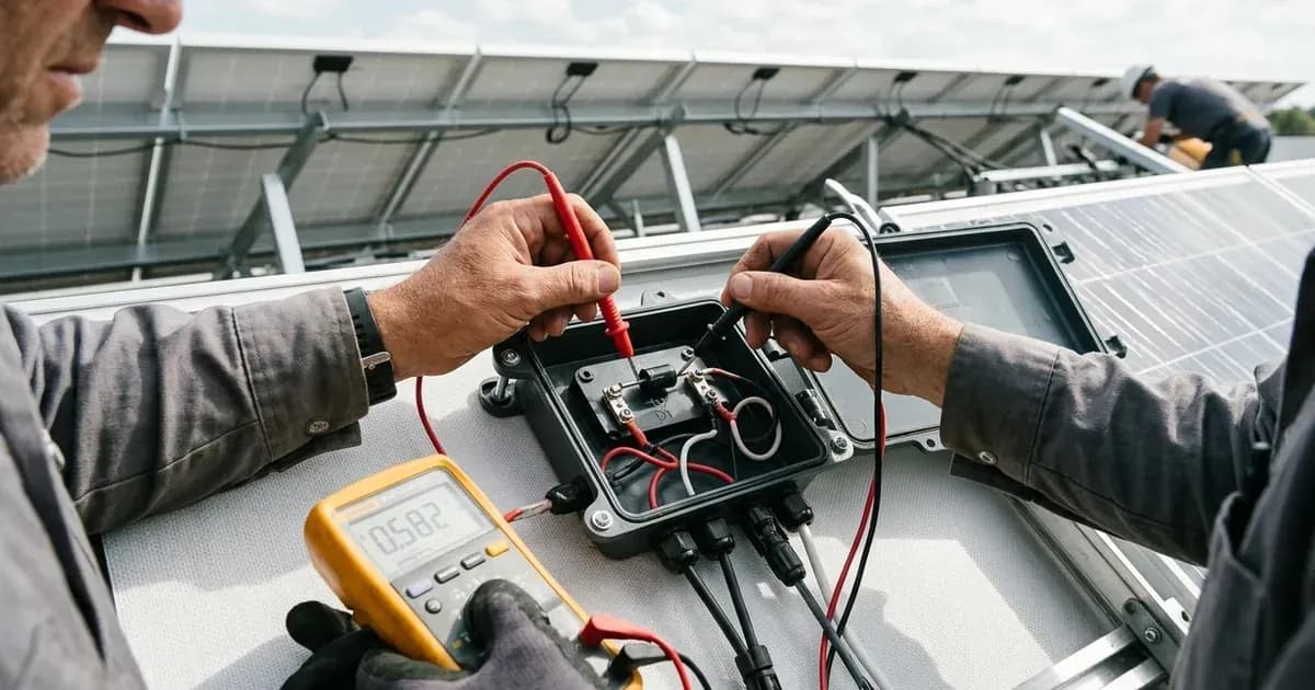
- Open Circuit Voltage (Voc) Measurement:
- What to check: Use a multimeter to measure the open circuit voltage (Voc) of the affected solar panel. Compare this reading to the expected Voc for your specific module model, which can be found in the manufacturer's datasheet. For example, the 605 Wp model from the Jinko Tiger Neo JKM580-605N-72HL4-(V) Series has a Voc of 53.11 V.
- What it means: If a bypass diode fails in a short circuit, it shorts a sub-string of cells. Commercial modules typically have three sub-strings within a module. This type of failure often results in a loss of one-third of the module’s voltage in open circuit (Voc). A significant drop in Voc, approximately one-third of the expected value, strongly indicates a short-circuited bypass diode.
- Safety note: Modules generate DC electrical energy when exposed to sunlight. Improper contact with live parts may result in burns, sparks, and lethal shock. Always cover the panel to block light before disconnecting or measuring.
- Thermal Imaging (Infrared Camera):
- What to check: Use a thermal camera to scan the surface of the solar panel and the junction box.
- What it means: Hot spots with strong local heat gradients can affect the performance of PV modules significantly. A sub-string of cells with a short-failed bypass diode may appear hotter than surrounding areas. Inactive areas of a module or string usually appear hotter than surrounding active areas.
- Note: Hot spots that arise from poor electrical connections or severe mismatch within a module are another important type of failure that is usually easily detectable using IR.
- Electroluminescence (EL) Imaging:
- What to check: EL imaging involves applying a forward current to the module in a darkened environment and capturing the emitted light with a specialized camera.
- What it means: When electroluminescence imaging is performed on a module, the entire sub-string of cells with a short-failed diode appears dark. This method provides insight into micro cracks and other defects within the cell material, resolving some defects more precisely than IR images. For best results, perform measurements at night to minimize extraneous light. For more details on this technique, refer to our guide on microcracks and EL detection.
- I-V Curve Tracing (for Open-Circuit Failures):
- What to check: This advanced technique involves plotting the current-voltage (I-V) curve of the module, especially under partial shading conditions.
- What it means: Open-circuit failures of bypass diodes are not easy to detect as they impact the module performance only under shading. Therefore, I-V tracing under partial shading or use of specialized equipment such as a diode checker is necessary in order to identify open failed diodes.
Cause/fix table
Symptom detail | Likely cause | Fix |
|---|---|---|
Module power loss (approx. 1/3 of total) | Bypass diode failed in short circuit | Replace the affected solar module. Bypass diodes are factory-installed and not typically field-replaceable. |
Hot spot on module surface | Bypass diode failed (open or short circuit), or prolonged partial shading | Identify and address the source of shading. If diode failure is confirmed, replace the module. |
Sub-string of cells appears dark in EL image | Bypass diode failed in short circuit | Replace the affected solar module. |
Reduced power output only under partial shading | Bypass diode failed in open circuit | Confirm with I-V tracing or a diode checker, then replace the module. |
Melted or discolored junction box | Overheating due to diode failure or incorrect wiring | Replace the module immediately. This indicates a significant safety hazard. |
Understanding Bypass Diode Failures
Bypass diodes are integrated into the junction box of solar modules, such as those from Jinko Solar. They are connected in parallel with each cell string to allow current to flow around shaded or faulty cells. This prevents hot spots and minimizes performance losses.
Bypass diodes can fail in two primary modes:
- Short Circuit Failure: When a bypass diode fails in a short circuit, it effectively shorts the sub-string of cells it is designed to protect. Typically, commercial modules have one diode per sub-string, with three sub-strings within a module. A short-circuit failure of one diode results in a one-third power loss for the module. This type of failure is relatively easier to detect, often causing a significant drop in the module's open circuit voltage (Voc) and appearing as a dark sub-string in electroluminescence images.
- Open Circuit Failure: When a bypass diode fails in an open circuit, it behaves as if the diode is not present across that sub-string. This condition is more challenging to detect because it only impacts module performance under shading. Without a functioning bypass diode, shaded cells can become reverse-biased, leading to hot spots and potential damage. Open circuit failures are regarded as safety risks.
Common causes of bypass diode failure include:
- Overheating: Prolonged operation under partial shading can cause diodes to spend significant time at high temperatures in forward bias, leading to failure. If the diode temperature exceeds its maximum rated temperature, the diode may undergo failure due to this single event of temperature over-stress.
- Thermal Cycling: In environments with recurrent partial shading, the temperature difference experienced by diodes can be much higher than that experienced by the modules. This large temperature fluctuation can cause diode failure by solder bond failures or crack propagation in the die itself.
- Manufacturing Defects: Electrostatic discharge (ESD) during manufacturing or high voltage spikes from equipment like flash testers can damage diodes.
- Incorrect Connections: If modules are incorrectly connected to each other, the bypass diodes, cables or junction boxes may be damaged.
It is important to note that a bypass diode is not an over-current protection device. For more information on hot spots, refer to our guide on hot spots in solar panels.
Safety: Working with Solar Panels
Working with solar panels involves significant electrical hazards. Always prioritize safety to prevent injury or damage.
- Lethal Shock Hazard: Modules generate DC electrical energy when exposed to sunlight or other light sources. Improper contact with live parts, such as terminals, may result in burns, sparks, and lethal shock.
- Disconnect Power: To prevent arcs and electrical shocks, do not disconnect modules under load without authorization. If disconnecting the connector is needed, turn off DC and AC inverters or cut off the main switch of the converter first.
- Cover Panels: PV module operation can only be stopped when they are kept from sunlight or covered by a hard board (opaque material) or UV-proof materials.
- Avoid Wet Conditions: Due to the risk of electrical shock, do not perform any work if the terminals of the module are wet. If work on wet modules is necessary, only proceed while wearing appropriate Personal Protective Equipment (PPE).
- Hot Surfaces: Do not touch the module, junction box, or the connectors with bare hands during installation or under sunlight. The glass surface and the frame may be hot, posing a risk of burns and electric shock.
- No Metal Objects: Do not insert any metal object into the connector.
- Fire Hazards: Do not install modules anywhere close to open flames or flammable materials (hay, straw, wood, solvents, oils, etc.), or exposed to flammable and explosive gases.
- Damaged Modules: Never attempt to clean a PV module with broken glass or other signs of exposed wiring, as this presents a shock hazard. Breakage of the front or rear glass can cause an electrical safety hazard, electric shock, or fire. These modules cannot be repaired and must be removed and replaced immediately.
When to call a technician instead
While some diagnostic steps can be performed by a homeowner or competent DIYer, certain situations necessitate professional intervention.
- Confirmed Diode Failure: If you have confirmed a bypass diode failure, especially a short-circuit, the entire solar module typically needs replacement. Bypass diodes are factory-installed within the junction box and are not designed for field replacement by end-users. Attempting to open the junction box or repair the diode yourself may void the module's warranty and pose significant safety risks.
- Melted Junction Box: Any sign of a melted or severely damaged junction box indicates a critical safety hazard. Immediately disconnect power to the affected string or system and contact a qualified solar technician.
- Lack of Specialized Tools: If you do not have access to specialized tools like thermal cameras, EL imaging equipment, or I-V curve tracers, accurately diagnosing open-circuit diode failures or subtle issues can be difficult. A professional technician will have the necessary equipment and expertise.
- Safety Concerns: If you are uncomfortable working with high-voltage DC electricity, or if the installation location is difficult or dangerous to access (e.g., a high roof), always defer to a trained and certified solar professional. They are equipped with the proper safety gear and training to handle such situations.
Still showing the fault? Book a technician
If the steps above did not clear it, tell us the inverter or battery and the exact code. We pass it to a technician who covers your city; visit charges are quoted before they come.
How this pays for the site: the technician or verifier pays SolarNevs a fixed introduction fee. Nobody pays to be recommended, and you are free to use our free guides instead.
Frequently asked questions
What is a bypass diode in a solar panel?
Jinko modules' junction boxes contain factory-installed bypass diodes connected in parallel with each cell string. These diodes allow current to flow around shaded or faulty cells, preventing hot spots and performance losses.
How does a bypass diode fail?
Bypass diodes can fail in two modes: short circuit or open circuit. Short circuit failures cause a partial power loss, while open circuit failures are more difficult to detect and primarily impact performance under shading.
What are the signs of a short-circuited bypass diode?
A short-circuited bypass diode often leads to a loss of one-third of the module’s open circuit voltage (Voc). The affected sub-string of cells may also appear dark when using electroluminescence imaging.
Can a failed bypass diode be a fire risk?
Yes, a failed bypass diode can no longer protect the module from hot spots, which could lead to fire risk. Melted junction boxes have been reported to cause vegetation fires in some cases.
How can I detect an open-circuited bypass diode?
Open-circuit failures are not easy to detect as they impact module performance only under shading. Therefore, I-V tracing under partial shading or use of specialized equipment such as a diode checker is necessary.
References
- JinkoSolar Global Installation Manual — accessed 23 August 2026
- PVEL Scorecard Failures — accessed 23 August 2026
- PV-Tech: PV bypass diode faults — accessed 23 August 2026
- IEA PVPS Review on IR and EL Imaging — accessed 23 August 2026
Related guides
More from inverter errors & fixes.