Troubleshooting One Solar String Producing Less Power Due to Shading or Mismatch
Updated 6 September 2026 · By SolarNevs Research Desk, Dealer surveys + verified sources · 5 sources · Method ↗
Key Takeaways
- Shading, module degradation, and faulty connections are the most likely causes for a string producing less power.
- A thorough visual inspection of all modules and wiring is the first step in diagnosis.
- Always de-energize the system and use insulated tools before touching electrical components.
- Electrical measurements (voltage and current) are essential to pinpoint the exact issue.
- Stop DIY troubleshooting and call a qualified technician if you encounter high voltages or cannot safely identify the problem.
What causes one solar string to produce less power?
When one string in your solar array produces less power than others, it typically points to an issue that restricts current flow or voltage within that specific string. The most common causes are shading, module degradation, or faulty electrical connections. The first thing to check is for any visible obstructions or damage to the panels in the underperforming string.
How to diagnose a low-producing solar string
Diagnosing a low-producing solar string requires a systematic approach, combining visual inspection with electrical measurements. Always prioritize safety when working with solar PV systems.
- Visual Inspection (Daylight):
- Check for Shading: Observe the entire string throughout the day. Look for any shadows cast by trees, buildings, antennas, or even accumulated dirt and debris on the panels. Partial shading on even one cell can significantly reduce a module's output, and thus the entire string's output.
- Inspect Modules for Damage: Look for visible damage such as cracked glass, discolored cells (often indicating hot spots), or delamination. Cell cracking, especially dendritic cracks, can lead to power loss.
- Check Wiring and Connections: Examine the DC wiring for any signs of damage, loose connections, or corrosion, particularly at the module-to-module connections and the junction box.
- Electrical Measurements (Daylight, full sun recommended):
- Safety First: Before performing any electrical measurements, ensure you understand the system's voltage and current ratings. Wear appropriate personal protective equipment (PPE), including insulated gloves and safety glasses.
- Measure String Open-Circuit Voltage (Voc):
- Disconnect the underperforming string from the inverter or charge controller.
- Use a multimeter set to DC voltage to measure the Voc across the positive and negative terminals of the disconnected string.
- Compare this reading to the Voc of a healthy string and the expected Voc based on your module's datasheet (e.g., for a Jinko Tiger Neo JKM580-605N-72HL4-(V) 605 Wp module, the Open-circuit Voltage (Voc) is 53.11 V at STC).
- A significantly lower Voc indicates a problem with one or more modules in the string, or a break in the circuit.
- Measure String Short-Circuit Current (Isc):
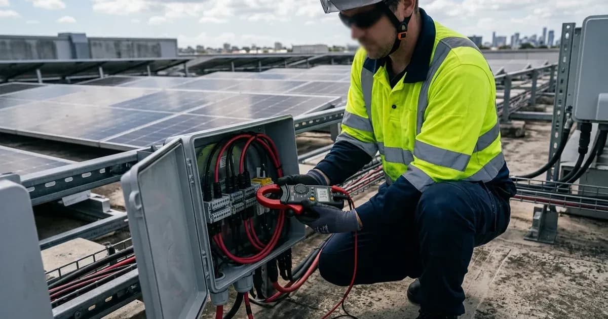
- With the string still disconnected from the inverter, carefully short the positive and negative terminals using a DC clamp meter capable of measuring high currents.
- Measure the Isc.
- Compare this reading to the Isc of a healthy string and the expected Isc from your module's datasheet (e.g., for a Jinko Tiger Neo JKM580-605N-72HL4-(V) 605 Wp module, the Short-circuit Current (Isc) is 14.31 A at STC).
- A significantly lower Isc often points to shading, module degradation, or a faulty bypass diode.
- Measure Individual Module Voltage and Current (if string measurements are off):
- If string measurements are abnormal, you may need to measure individual modules. This involves disconnecting modules within the string, which can be complex and requires extreme caution due to high voltages.
- Measure the Vmp and Imp of each module. Compare these to the datasheet values (e.g., for a Jinko Tiger Neo JKM580-605N-72HL4-(V) 605 Wp module, the Maximum Power Voltage (Vmp) is 44.23 V and Maximum Power Current (Imp) is 13.68 A at STC).
- Significant deviations indicate a problem with that specific module.
- Thermal Imaging (Optional but Recommended): An infrared (IR) camera can quickly identify hot cells or hot spots on modules, which often indicate internal defects, shading, or bypass diode failures. Hot cells can reach temperatures exceeding 150°C and are a sign of power dissipation. Open-circuit substrings or module strings can appear 5-10 K hotter in IRT inspection compared to active strings.
Common causes and fixes for string mismatch
Symptom detail | Likely cause | Fix |
|---|---|---|
String output consistently lower than others | Shading from external objects (trees, buildings, debris) | Remove the obstruction. Clean modules if soiling is the cause. Consider re-orienting panels or trimming vegetation. |
Discolored cells or visible burn marks on a module | Hot cells due to partial shading, cell cracking, or high resistive interruption | Identify the cause of the hot cell. If due to external shading, remove it. If due to internal module defect (cracking, bypass diode failure), the module may need replacement. |
Cracks visible on solar cells within a module | Cell cracking (micro cracks growing into dendritic cracks) | If cracks are extensive and causing significant power loss, the module may need replacement. For multi-wire solar modules, 0.2% power loss per dendritic-like cracked half-cell has been observed. |
Loose or corroded wiring at module connectors or junction box | Unreliable junction box connections or damaged wiring | Isolate the circuit. Clean and re-tighten all connections. Replace damaged connectors or wiring. Ensure proper sealing of the junction box (e.g., Trina Solar Vertex NEG21C.20 modules have an IP 68 rated J-Box). |
All modules in a string appear fine, but output is low | Degradation modes like PID, LeTID, or UVID affecting the entire string | These are complex issues. PID-p in TOPCon modules with EVA encapsulation can rapidly and repeatedly recover under sunlight when the voltage potential across the front glass is removed. Consider professional diagnosis and potential module replacement if degradation is severe. |
Bypass diode failure in a module | A faulty bypass diode causes the entire shaded or faulty section of cells to drop out | Use thermal imaging to identify hot spots or measure individual module current. Replace the faulty bypass diode if accessible, or replace the module. |
Understanding PV module performance
Solar PV modules convert sunlight into electricity, and their performance is defined by several key electrical parameters measured under Standard Test Conditions (STC: Irradiance 1000W/m², Cell Temperature 25°C, AM=1.5).
- Maximum Power (Pmax): The highest power output a module can achieve. For example, a Jinko Tiger Neo JKM580-605N-72HL4-(V) series module can have a Pmax of 605 Wp.
- Maximum Power Voltage (Vmp): The voltage at which the module produces its maximum power. For a Jinko Tiger Neo JKM580-605N-72HL4-(V) 605 Wp module, this is 44.23 V.
- Maximum Power Current (Imp): The current at which the module produces its maximum power. For the same Jinko module, this is 13.68 A.
- Open-circuit Voltage (Voc): The maximum voltage produced by the module when no load is connected. For a Jinko Tiger Neo JKM580-605N-72HL4-(V) 605 Wp module, this is 53.11 V.
- Short-circuit Current (Isc): The maximum current produced by the module when its terminals are short-circuited. For the same Jinko module, this is 14.31 A.
These values are crucial for understanding how a string should perform. When modules are connected in series to form a string, their voltages add up, but the current is limited by the lowest-performing module.
Temperature Effects: PV module performance is affected by temperature. For instance, Jinko Tiger Neo JKM580-605N-72HL4-(V) modules have a Temperature Coefficient of Pmax of -0.29%/°C, meaning their power output decreases by 0.29% for every degree Celsius above 25°C. Similarly, the Temperature Coefficient of Voc is -0.25%/°C and Isc is 0.045%/°C. Operating temperatures for these modules range from -40°C to +70°C.
Degradation Modes Affecting Output: Several degradation mechanisms can lead to reduced string output:
- Hot Cells: Localized or homogeneous temperature rise in solar cells, potentially exceeding 150°C, caused by current mismatch or reverse bias voltages. This can result from partial shading, high resistive interruptions, or cell cracking. Hot cells can lead to discoloration, interconnection failures, cell cracks, and delamination. Manufacturers incorporate bypass diodes (BPDs) to minimize the formation of hot cells.
- Cell Cracking: Micro cracks, often at the cutting cell edge, can grow into dendritic cracks during transportation, installation, or mechanical/temperature stress. These cracks can cause power loss.
- Unreliable Junction Box Connections: Failures in the junction box connections can lead to open-circuit substrings or module strings, which appear 5-10 K hotter in IRT inspection compared to active strings. These can cause power losses and even arcs or fire.
- Potential-Induced Degradation (PID): Power loss in PV modules due to electric charge transfer through encapsulation. This is influenced by voltage potential, polarity, and environmental factors. PID-polarization (PID-p) is a common type, with 83% of PID power loss failures attributed to it, as commonly reported by installers.
- Light and Elevated Temperature-Induced Degradation (LeTID): Power degradation under combined thermal and light stress, followed by slow recovery. This can lead to significant yield loss, sometimes over 10% in field operation. Modules containing n-type TOPCon cells are substantially less susceptible to LeTID than early p-doped PERC cells.
- UV-Induced Degradation (UVID): High degradation rates in accelerated UV degradation tests for modern cell types like TOPCon. A study of 14 TOPCon types showed power loss from 0.5% to 8% (median 3%) after 60 kWh/m² UV dose under short-circuit conditions.
Safety: Working with PV systems
Working with solar PV systems involves significant electrical hazards. Always adhere to safety guidelines to prevent injury or damage.
- De-energize the System: Before performing any work on PV modules or wiring, ensure the entire system is de-energized. This includes isolating the PV array from the inverter and disconnecting any batteries.
- High Voltage: Solar strings can produce high DC voltages, up to 1000/1500 VDC (IEC) for Jinko Tiger Neo modules or 1500V (IEC/UL) for Canadian Solar TOPHiKu6 modules. Always assume wires are live.
- Insulated Tools and PPE: Use only insulated tools and wear appropriate personal protective equipment, including insulated gloves, safety glasses, and non-conductive footwear.
- Short Circuits: Avoid creating short circuits. A spanner across a live PV string can cause a dangerous arc flash.
- Junction Boxes: Ensure junction boxes are properly sealed (e.g., IP 68 rated for Trina Solar Vertex NEG21C.20 modules) to prevent moisture ingress, which can lead to connection failures.
- Qualified Personnel: PV modules should be handled and installed by qualified people who have professional skills. Always read the safety and installation instructions before using PV modules.
When to call a technician instead
While some basic troubleshooting can be performed by a homeowner, there are clear limits to DIY work. You should call a qualified solar technician if:
- You are uncomfortable working with high DC voltages.
- You cannot safely access the solar panels or wiring.
- Your visual inspection and basic electrical measurements do not clearly identify the problem.
- The issue appears to be internal to a module (e.g., severe hot spots, extensive cell cracking, or suspected PID/LeTID).
- You suspect a fault within the inverter or other balance-of-system components.
- The problem involves complex wiring or system configuration.
- Your system is still under warranty, as improper DIY repairs could void it.
A professional technician has specialized tools, training, and experience to diagnose and safely repair complex solar PV system issues.
Still showing the fault? Book a technician
If the steps above did not clear it, tell us the inverter or battery and the exact code. We pass it to a technician who covers your city; visit charges are quoted before they come.
How this pays for the site: the technician or verifier pays SolarNevs a fixed introduction fee. Nobody pays to be recommended, and you are free to use our free guides instead.
Products mentioned
Frequently asked questions
What is solar string mismatch?
Solar string mismatch occurs when individual modules within a series-connected string produce different amounts of current or voltage. This can be caused by shading, varying degradation rates, or manufacturing differences, leading to reduced overall string output.
How does shading affect a solar string's output?
Shading on even a small part of a solar panel can significantly reduce the current output of the entire string it belongs to. Shaded cells can become hot cells, dissipating power as heat and further reducing efficiency.
Can a single faulty solar panel reduce the output of an entire string?
Yes, a single faulty solar panel, such as one with cell cracking or an unreliable junction box connection, can act as a bottleneck, reducing the current flow and thus the power output of all other panels in the same series string.
What tools are essential for troubleshooting a low-producing solar string?
Essential tools include a multimeter for measuring voltage and current, and a clamp meter for measuring current in individual strings. An infrared camera can help identify hot cells or faulty connections.
When should I replace a module in a low-producing string?
Consider replacing a module if diagnostic tests confirm it is consistently underperforming due to irreversible damage like extensive cell cracking, severe hot-spot damage, or if it's causing significant power loss across the entire string that cannot be otherwise mitigated.
References
- Jinko Tiger Neo JKM580-605N-72HL4-(V) Datasheet — accessed 23 August 2026
- Canadian Solar TOPHiKu6 CS6.1-72TD Series Datasheet — accessed 23 August 2026
- Trina Solar Vertex NEG21C.20 Series Datasheet — accessed 23 August 2026
- IEA-PVPS T13-30-2025-REPORT-Degradation-and-Failure — accessed 23 August 2026
- PVEL Scorecard PID — accessed 23 August 2026
Related guides
More from inverter errors & fixes.