Orient Inverter AC Error Code List: J-SMART Series Troubleshooting
Updated 7 September 2026 · By SolarNevs Research Desk, Dealer surveys + verified sources · 1 source · Method ↗
Key Takeaways
- Orient J-SMART Inverter AC error codes pinpoint specific issues, often related to sensors, motors, or communication.
- Always begin troubleshooting by checking the power supply and all electrical connections.
- Mains voltage is present inside AC units; always isolate power at the breaker and wait before opening covers.
- Errors indicating module, compressor, or PCB failures typically require a qualified technician.
What do Orient J-SMART Inverter AC error codes mean?
Orient J-SMART Inverter AC error codes indicate specific faults within the indoor or outdoor units, often related to sensors, motors, or communication. These codes help you or a technician identify the problem area quickly, such as E1 for an indoor temperature sensor error or E5 for a communication fault between units. Understanding these codes is the first step in diagnosing and resolving issues with your air conditioner.
Diagnosis
When your Orient J-SMART Inverter AC displays an error code, follow these steps to diagnose the issue safely.
- Note the Error Code: Observe the exact code displayed on the indoor unit or the blink pattern on the outdoor unit LEDs. This code is your primary diagnostic clue.
- Power Cycle the Unit: Turn off the AC unit at the main breaker for at least 5 minutes, then turn it back on. This can sometimes clear temporary glitches.
- Check Power Supply: Ensure the AC is receiving stable power within its specified operating range of 220-240V-1-50Hz. The normal supply voltage should be between 198V and 242V. Fluctuations outside the minimum work assurance range of 165V to 265V can trigger protection errors like F7 (OVP or UVP).
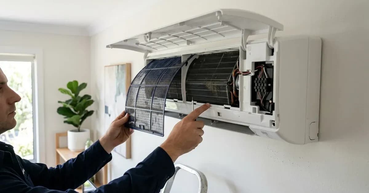
- Inspect Air Filters and Obstructions: Clogged air filters or blocked outdoor unit coils can restrict airflow, leading to protection errors like P4 (Refrigeration Overload Protection) or P6 (Indoor High Temperature Protection). Clean or clear any obstructions.
- Examine Visible Wiring and Connections: For communication errors (E5) or sensor errors (E1, E2, E3, F4, F5, F6), visually inspect the wiring between the indoor and outdoor units, as well as sensor wires, for any signs of damage, loose connections, or corrosion.
- Listen for Unusual Noises: Sounds like grinding, buzzing, or clicking can indicate issues with motors (E4, F0) or the compressor (F3, L2).
- Consult the Error Code Table: Match the observed error code to the table below for its meaning and initial fix direction. This will guide you on whether the issue is a simple fix or requires professional intervention.
Cause/fix table
The following table lists common error codes for the Orient J-SMART Inverter Split-Type Air Conditioner series, their meanings, and general fix directions.
Code | Meaning | Fix Direction |
|---|---|---|
E0 | Overcurrent Protection of Indoor Unit | Check current transformer, power line, compressor line, and connector assembly. |
E1 | Indoor Unit temperature sensor error | Inspect sensor, sensor wire, connectors, and Indoor Unit main PCB. |
E2 | Outdoor Unit coil sensor error | Inspect sensor, sensor wire, connectors, and Outdoor Unit main PCB. |
E3 | Indoor Unit coil sensor error | Inspect sensor, sensor wire, connectors, and Indoor Unit main PCB. |
E4 | Indoor Unit motor error (PG or DC motor) | Check if motor is stuck, speed feedback line, motor terminal connectors, and Indoor Unit main PCB. |
E5 (5E) | Indoor Unit and Outdoor Unit communication error | Verify Outdoor Unit power, unit matching, and AC 220V delivery to Outdoor Unit terminal block. |
Eb | Indoor EE Failure | Inspect Indoor Unit main PCB. |
F0 | Outdoor Unit DC motor error (3-core terminal motor) | Check if motor is stuck, motor terminal connectors, Outdoor Unit main PCB, and motor. |
F1 | Module protection error | Inspect supply voltage, compressor wire, reactor wire, system blockage, module panel, Outdoor Unit main PCB, and compressor. |
F2 | PFC protection error | Inspect supply voltage, AC and DC power path, PFC board data wire, PFC board, and Main PCB. |
F3 | Compressor out-of-step error | Inspect supply voltage, compressor wire, reactor wire, system blockage, module panel, Outdoor Unit main PCB, and compressor. |
F4 | Exhaust sensor error | Inspect exhaust sensor, sensor wire, connectors, and Outdoor Unit main PCB. |
F5 | Compressor top head sensor error | Inspect compressor top head sensor (temperature protection switch), sensor wire, connectors, and Outdoor Unit main PCB. |
F6 | Outdoor Unit temperature sensor error | Inspect sensor, sensor wire, connectors, and Outdoor Unit main PCB. |
F7 | OVP or UVP error | Inspect supply voltage, Indoor Unit direct current voltage, reactor wiring, module panel, and Outdoor Unit main PCB. |
F8 | Outdoor Unit main PCB and module panel communication error | Check data line connection, module panel power, module panel, and Outdoor Unit main PCB. |
F9 | Outdoor EE error | Inspect Outdoor Unit main PCB. |
FA | Recirculated sensor error | Inspect four-way valve, recirculated sensor, sensor wire, connectors, and Outdoor Unit main PCB. |
P2 | High-pressure protection | Check high-pressure switch cable, connector, high-pressure switch, and main PCB. |
P3 | Liquid Deficiency Protection | Verify outdoor unit valves are open, check for damage/cracks in evaporator/condenser/pipes, and check environmental/coil temperature sensors. |
P4 | Refrigeration Overload Protection | Check for system dirt/blockage, dirty condenser, Outdoor Unit coil sensor, AC motor running, and controller divider resistance. |
P5 | Exhaust Protection | Inspect system pressure, indoor/outdoor air inlet, exhaust sensor, and Outdoor Unit panel. |
P6 | Indoor High Temperature Protection | Inspect indoor air inlet, indoor unit filter, indoor motor, and indoor coil sensor. |
P7 | Anti-freezing Protection in Refrigeration Room | Inspect indoor air inlet, indoor unit filter, indoor motor, and indoor coil sensor. |
P8 | Overcurrent Protection | Inspect system blockage, grid voltage, and outdoor unit controller. |
L0 | DC Over/Under-voltage Failure | Inspect Outdoor unit controller and power grid. |
L1 | Overcurrent Protection on Phase Current of Compressor | Inspect Outdoor unit controller, power grid, compressor, and compressor wire. |
L2 | Out-of Step Failure of Compressor | Inspect Outdoor unit controller, power grid, compressor, and system pressure. |
L3 | Phase Failure of Compressor | Inspect Outdoor unit controller, power grid, compressor, and compressor wire. |
L4 | Driver Module IPM Failure of Compressor | Inspect Outdoor unit controller, power grid, and compressor. |
L5 | PFC Overcurrent Hardware Protection | Inspect Outdoor unit controller and power grid. |
L6 | PFC Overcurrent Software Protection | Inspect Outdoor unit controller and power grid. |
L7 | AD Abnormal Protection in Current Detection | Inspect Outdoor unit controller. |
L8 | Shunt Resistance Imbalance Failure | Inspect Outdoor unit controller. |
L9 | IPM Temperature Sensor Failure | Inspect Outdoor unit controller. |
LA | Compressor Startup Failure | Inspect Outdoor unit controller, power grid, compressor, and compressor wire. |
LC | AD Abnormal Protection in PFC Current Detection | Inspect Outdoor unit controller. |
Orient J-SMART Inverter AC Specifics
Outdoor Unit LED Blink Patterns (J-SMART Inverter Split-Type AC)
The outdoor unit of your Orient J-SMART Inverter AC uses a series of LED lights (LED1, LED2, LED3) to indicate operational status and fault conditions. These patterns can help diagnose issues even without a digital display.
Status/Error | LED1 | LED2 | LED3 |
|---|---|---|---|
Normal (outdoor unit standby) | ○ | ○ | ○ |
Normal (compressor running) | ★ | ★ | ★ |
Forced service (test mode) | ● | ● | ● |
Module protection error | ★ | ★ | ● |
PFC protection error | ★ | ★ | ○ |
Compressor out-of-step error | ★ | ● | ★ |
Exhaust air sensor error | ★ | ○ | ★ |
External coil sensor error | ● | ★ | ★ |
External room temperature sensor error | ○ | ★ | ★ |
Indoor and outdoor unit communication error | ★ | ● | ● |
Outdoor Unit main PCB and module panel communication error | ★ | ● | ○ |
Outdoor EE error | ★ | ○ | ● |
Outdoor DC motor error | ★ | ○ | ○ |
Indoor Unit room temperature sensor error | ● | ★ | ● |
Indoor Unit coil sensor error | ● | ★ | ○ |
Indoor motor error | ○ | ★ | ● |
Refer to tooling display for other errors | ○ | ★ | ○ |
Compressor cap sensor error | ● | ● | ★ |
Recirculated sensor error | ● | ○ | ★ |
Compressor overpower protection | ○ | ● | ★ |
Over current protection | ○ | ○ | ★ |
Exhaust sensor error | ● | ● | ○ |
Cooling overload protection | ● | ○ | ● |
Indoor high temperature heating protection | ○ | ● | ● |
Indoor cooling freezing protection | ● | ○ | ○ |
Compressor shell temperature protection | ○ | ● | ○ |
OVP or UPV error | ○ | ○ | ● |
<br>
Legend: ★ = Flashing, ● = On, ○ = Off
Inverter-Drive and Bus-Voltage Codes
Orient J-SMART ACs are inverter-type units, which means they have sophisticated control systems that monitor various electrical parameters. Errors related to these systems often indicate issues with the power electronics or compressor.
- L0 (DC Over/Under-voltage Failure): This code points to issues with the DC voltage levels within the outdoor unit controller or the power grid supply.
- F1 (Module protection error): This broad error can involve the supply voltage, compressor wiring, reactor wiring, system blockages, module panel damage, or even a destroyed Outdoor Unit main PCB or compressor.
- F2 (PFC protection error): Relates to the Power Factor Correction circuit, indicating issues with the supply voltage, AC/DC power path, PFC board data wire, PFC board, or Main PCB.
- F3 (Compressor out-of-step error): This indicates the compressor is not running smoothly. It can be caused by supply voltage issues, compressor/reactor wiring, system blockages, module panel damage, or a damaged Outdoor Unit main PCB or compressor. When troubleshooting F3, check if the DC voltage between P-N is too high (above 200V).
- F7 (OVP or UVP error): This code specifically refers to Over Voltage Protection or Under Voltage Protection. It monitors the supply voltage, indoor unit direct current voltage, reactor wiring, module panel, and the Outdoor Unit main PCB. When the compressor is running, the voltage between P and N ends detected on the test module panel or Outdoor Unit main PCB should be over 200V.
- P8 (Overcurrent Protection): This code indicates the controller detects the AC bus current exceeding a set protection value. Potential causes include system blockage, grid voltage issues, or problems with the outdoor unit controller.
- L1, L2, L3, L4, L5, L6, L7, L8, L9, LA, LC: These 'L' series codes are detailed inverter-drive protection errors, covering various aspects like compressor phase current overcurrent (L1), compressor out-of-step (L2), phase failure (L3), IPM failure (L4), PFC overcurrent (L5, L6), current detection abnormalities (L7), shunt resistance imbalance (L8), IPM temperature sensor failure (L9), compressor startup failure (LA), and PFC current detection abnormalities (LC). These typically point to internal component failures within the outdoor unit's controller, compressor, or power grid interactions.
Running Your Orient J-SMART AC on Solar or UPS
Orient J-SMART Inverter ACs are designed to operate within specific electrical parameters. When integrating with solar or UPS systems, it's crucial to ensure these requirements are met to prevent errors and damage.
- Operating Voltage and Frequency: All J-SMART models require a power supply of 220-240V-1-50Hz. The normal supply voltage must be between 198V and 242V.
- Voltage Tolerance: The air conditioner has a minimum work assurance range between 165V and 265V. Operating outside this range, or with frequent fluctuations, can trigger OVP or UVP errors (F7).
- Inverter Technology: As "J-SMART Inverter Split-Type Air Conditioners," these units feature inverter technology, which allows for variable compressor speed. This generally means a softer start-up compared to fixed-speed units, reducing inrush current demands. However, specific inrush current figures are not published in the provided manual.
- Unstable Power Supply Behavior: The manual notes that the AC includes protection for unstable power environments. If you experience protection prompts, especially OVP and UVP errors (F7), it often signifies issues with the power supply quality from your solar inverter or UPS. The system monitors DC bus voltage (should be over 200V when compressor is running for F3 and F7 errors) and AC bus current (P8). Ensure your solar inverter or UPS can provide a stable output within the specified voltage and frequency ranges, especially under varying load conditions.
Safety
Working with air conditioning units involves high voltage and refrigerant. Always prioritize safety.
- Electrical Isolation: Before performing any inspection or maintenance, always turn off the AC unit at the main breaker. The indoor unit's terminal block operates at the supply voltage (220-240V), and the outdoor unit contains capacitors that can hold a charge after shutdown. Wait for the manual's specified capacitor discharge time (if available, otherwise at least 5-10 minutes) before touching any internal components.
- Rated Voltage and Circuit: Ensure your AC is connected to a dedicated circuit with the rated voltage and that the power cord diameter meets national requirements.
- Protection Devices: If the maximum current of your air conditioner is 16A or more, it must use an air switch or leakage protection switch equipped with appropriate protection devices.
- Grounding: The air conditioner is a Type I electrical appliance and requires reliable grounding. Do not connect the grounding wire to gas pipes, water pipes, lightning rods, telephone lines, or poorly grounded circuits.
- High Voltage Warning: Be aware that certain internal wires, such as the fifth (red) wire mentioned in the manual, carry a strong voltage of 310V under normal conditions. Exercise extreme caution to avoid electric shock.
- Combustible Clearance: Maintain a minimum clearance of 1.5 meters between the air conditioner and any combustible materials.
When to call a technician instead
While some basic troubleshooting can be performed, many Orient J-SMART Inverter AC errors require professional expertise. You should call a qualified HVAC technician if:
- The error code persists after basic power cycling and visual checks.
- The error points to internal component failures such as module protection (F1), PFC protection (F2), compressor issues (F3, L1-LA), or main PCB errors (Eb, F9).
- You need to open the outdoor unit or access high-voltage components. Opening the unit for internal repairs is authorized service work and can void your warranty if not performed by a certified professional.
- You suspect refrigerant leaks (P3, FA) or issues with high-pressure systems (P2, P5).
- You are uncomfortable or unsure about any diagnostic or repair step. Electrical work, especially with high-voltage appliances like ACs, carries significant risk.
Still showing the fault? Book a technician
If the steps above did not clear it, tell us the inverter or battery and the exact code. We pass it to a technician who covers your city; visit charges are quoted before they come.
How this pays for the site: the technician or verifier pays SolarNevs a fixed introduction fee. Nobody pays to be recommended, and you are free to use our free guides instead.
Frequently asked questions
What does E5 mean on an Orient J-SMART Inverter AC?
E5 (or 5E) on an Orient J-SMART Inverter AC indicates a communication error between the indoor and outdoor units. This often points to issues with the connection wiring or one of the main PCBs.
How do I troubleshoot an E1 error on my Orient J-SMART Inverter AC?
An E1 error means there is an indoor unit temperature sensor error. You should check the sensor itself, its wiring, and the connectors to the indoor unit's main PCB for any damage or loose connections.
What is the operating voltage range for Orient J-SMART Inverter ACs?
Orient J-SMART Inverter ACs operate with a power supply of 220-240V-1-50Hz. The normal supply voltage should be between 198V and 242V, with a minimum work assurance range of 165V to 265V.
What do the LED blink patterns on the Orient J-SMART outdoor unit indicate?
The outdoor unit LEDs (LED1, LED2, LED3) on an Orient J-SMART AC provide diagnostic information. For example, all three LEDs flashing indicates the compressor is running normally, while specific patterns like LED1: ★, LED2: ★, LED3: ● point to a module protection error.
What does an F7 error mean on an Orient J-SMART Inverter AC?
An F7 error on an Orient J-SMART Inverter AC signifies an OVP (Over Voltage Protection) or UVP (Under Voltage Protection) error. This suggests issues with the supply voltage, Indoor Unit direct current voltage, reactor wiring, module panel, or the Outdoor Unit main PCB.
References
- J-SMART Inverter Split-Type Air Conditioner Manual — accessed 23 August 2026
Related guides
More from inverter errors & fixes.