Solis Energy Storage High Voltage Battery Setup Guide
Updated 7 September 2026 · By SolarNevs Research Desk, Dealer surveys + verified sources · 3 sources · Method ↗
Key Takeaways
- Always ensure complete AC circuit isolation and lock-out before working on electrical components.
- Proper earthing of the inverter chassis and battery enclosure is a critical safety step.
- Correct installation and orientation of Current Transformer (CT) clamps are essential for accurate system operation.
- Verify RS485 communication settings and cabling for reliable system performance.
Understanding Solis High-Voltage Energy Storage Systems
Solis high-voltage energy storage systems are engineered for both residential and commercial off-grid and grid-parallel applications worldwide. These systems are compatible with standard single-phase and three-phase electrical distribution systems globally. They comply with international microgeneration safety and grid protection standards, ensuring safe and effective integration into your property's electrical infrastructure.
The ESS assistant within these systems dynamically manages battery charge and discharge based on grid tariffs and load. This intelligent management helps optimise energy usage and can contribute to energy savings.
Essential Safety and Earthing Procedures
Safety is paramount when installing any high-voltage energy storage system. Before beginning any work, ensure complete AC circuit isolation and lock-out, especially when installing Current Transformer (CT) clamps on live busbars. This prevents accidental energisation and reduces the risk of electrical shock.
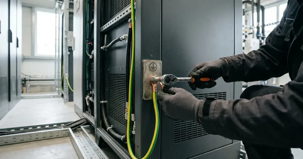
A critical safety step is proper earthing. You must bond the inverter chassis ground and battery metal enclosure to the main installation earthing terminal. This provides a safe path for fault currents, protecting both the equipment and personnel. All DC conductors, AC feeders, and auxiliary control cables must be installed in compliance with applicable national electrical codes and verified by an accredited electrical engineer.
Installing Current Transformer (CT) Clamps
Current Transformer (CT) clamps are vital for the energy storage system to accurately monitor household consumption and grid interaction. Correct installation is crucial for the system's performance.
Install Current Transformer clamps with arrows pointing towards the household loads, away from the grid incomer. This ensures the system correctly interprets the direction of energy flow. If you observe negative power flow during high household consumption, it indicates an inverted CT clamp installation, which will need to be corrected.
Setting Up RS485 Communication
Reliable communication between the Solis inverter and the high-voltage battery system is essential for proper operation. This communication typically occurs via RS485.
To ensure stable communication, maintain shielded twisted-pair cabling for all RS485 connections. You must also verify proper RS485 communication baud rate settings. Incorrect settings can lead to communication errors, preventing the system from operating efficiently or at all. Consult the specific Solis product manual for the recommended baud rate and wiring diagrams.
Pre-Commissioning Checks and Verification
Before finally energising your Solis high-voltage energy storage system and obtaining utility permission to operate, a series of pre-commissioning checks are mandatory. These steps ensure the system is installed correctly and safely.
These checks include:
- Pre-commissioning checks: A thorough review of all physical connections and component installations.
- Insulation resistance testing: Verifying the integrity of electrical insulation to prevent short circuits and electrical hazards.
- Polarity verification: Confirming that all DC and AC connections have the correct polarity.
These steps are critical for the long-term reliability and safety of the installation. An MCS Certificate is required to access export tariffs and verify building regulations compliance in Great Britain.
What you can check yourself, and what you cannot
Inspection / Task | Homeowner Scope | Professional Requirement |
|---|---|---|
Cable & enclosure visual check | Visual inspection for loose cables and chassis ground bonding | Torque verification and internal terminal checks |
CT clamp verification | Check direction arrow points toward household loads | Reorientation and live busbar clamp handling |
Insulation resistance & polarity | Not permitted (high-voltage hazard) | Testing and sign-off by accredited electrical engineer |
Grid-protection & communication settings | Not permitted (risk of breaching connection agreement) | Authorized installer configuration |
Enclosure opening & internal wiring | Not permitted (warranty and safety restriction) | Authorized service technician |
As a homeowner, you can visually inspect the installation for obvious issues like loose cables or incorrect CT clamp orientation (checking the arrow direction). You can also verify that the inverter and battery enclosures are securely earthed to the main earthing terminal.
However, any work involving live electrical circuits, internal wiring, or verification of electrical parameters (like insulation resistance or baud rate settings) must be performed by an accredited installer or a qualified electrical engineer. Changing inverter settings, especially grid-protection settings, can breach your connection agreement and should only be done by a certified professional. Opening the battery enclosure or inverter unit is authorised-service work and should not be attempted by homeowners.
What the published sources do not tell you
The provided information offers general safety and installation principles but lacks specific technical details for Solis high-voltage lithium battery systems. For instance, it does not specify:
- Specific DC isolator wiring diagrams: published guidance does not provide detailed instructions or diagrams for connecting DC isolators to Solis high-voltage batteries.
- Series cell balancing procedures: There is no information on how series cell balancing is managed within Solis high-voltage battery packs or if any user intervention is required.
- Exact safety clearance values: published guidance does not provide specific minimum clearance distances required around the battery or inverter for ventilation or safety.
- Detailed manufacturer equipment ratings: While general compatibility is mentioned, specific power ratings, voltage ranges, or current limits for Solis high-voltage batteries are not included.
- Specific RS485 pinouts or baud rate values: While verifying settings is mentioned, the actual values or wiring configurations are not provided.
For these specific details, you must consult the official Solis product manuals and installation guides relevant to your specific model of high-voltage battery and inverter. These documents contain the precise technical specifications and step-by-step instructions necessary for a compliant and safe installation.
Still showing the fault? Book a technician
If the steps above did not clear it, tell us the inverter or battery and the exact code. We pass it to a technician who covers your city; visit charges are quoted before they come.
How this pays for the site: the technician or verifier pays SolarNevs a fixed introduction fee. Nobody pays to be recommended, and you are free to use our free guides instead.
Frequently asked questions
What are the primary technical requirements for solis energy storage high voltage battery setup guide?
Key requirements include compliance with local grid codes, correct equipment certification, and proper electrical isolation.
Who is authorized to install and inspect solis energy storage high voltage battery setup guide?
All high-voltage DC, AC grid tie-in, and switchboard modifications must be performed by a qualified, accredited electrical professional.
How is export power limited in solis energy storage high voltage battery setup guide?
Export limiting is achieved using certified bidirectional smart meters or power sensors providing dynamic feedback to the inverter system.
References
- SolisStorage FlexHome-(15-40)kWh-H Quick Installation Manual (PDF, April 2026) - qualified-personnel, battery grounding, clearance and CAN/RS485 communication requirements — accessed 6 September 2026
- Solis Service Centre - Communication ports for battery connection (CAN/RS485 pinouts for high-voltage and low-voltage batteries on Solis hybrid inverters) — accessed 6 September 2026
- NEPRA (Prosumer) Regulations 2026, SRO 251(I)/2026 (PDF) - application, interconnection agreement and concurrence process for grid-connected distributed generation in Pakistan — accessed 6 September 2026
Related guides
More from inverter errors & fixes.