Solis S6 Three Phase High Voltage Hybrid Inverter Setup Guide
Updated 7 September 2026 · By SolarNevs Research Desk, Dealer surveys + verified sources · 4 sources · Method ↗
Key Takeaways
- Solis S6-EH3P inverters are designed for three-phase high-voltage battery storage systems, compatible with Pylontech Force-H2.
- BMS communication requires a dedicated CAN cable connection to the inverter and specific 500kbps baud rate DIP switch settings for Pylontech Force-H2.
- Essential circuits connect to a dedicated EPS backup port for automated off-grid power during outages.
- Always follow the safe DC battery disconnect procedure, waiting at least 5 minutes for internal capacitor discharge.
Setting Up Your Solis S6 Three-Phase Hybrid Inverter
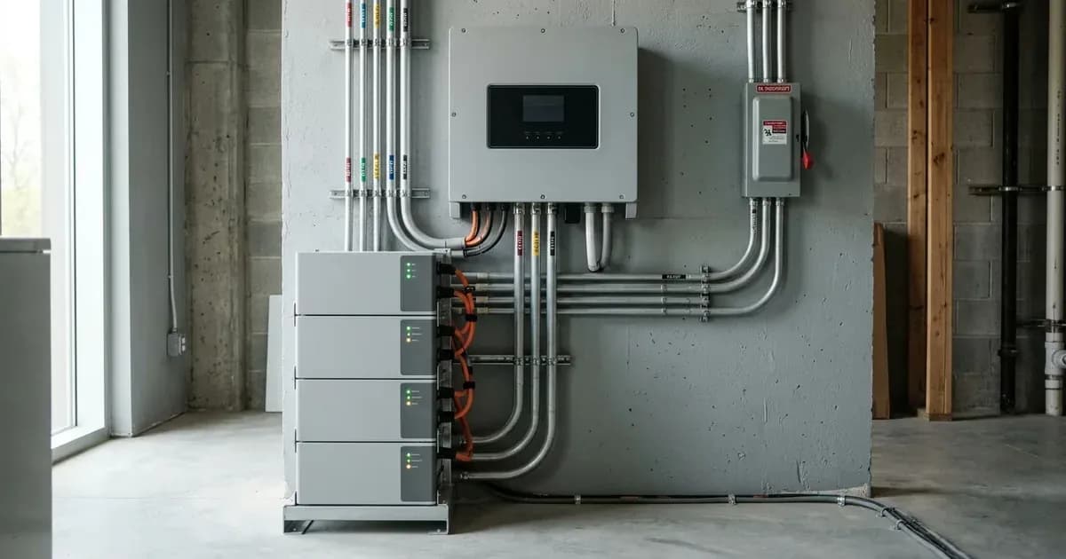
This guide details the setup for the Solis S6-EH3P(5-10)K-H-EU three-phase high-voltage hybrid inverters with Pylontech Force-H2 storage. It covers essential wiring, communication, and commissioning steps to ensure a safe and functional installation. The Solis S6 three-phase hybrid inverters interface with high-voltage lithium battery storage for maximum round-trip efficiency.
Understanding the Solis S6-EH3P System
The Solis S6-EH3P(5-10)K-H-EU is engineered for both residential and commercial off-grid and grid-parallel energy storage systems worldwide. It is compatible with standard single-phase and three-phase electrical distribution systems globally. A key feature is its ability to deliver up to 100% unbalanced AC power output per phase, supporting asymmetric household and commercial loads. The system also includes certified anti-islanding protection, complying with international microgeneration safety and grid protection standards.
Essential Wiring and Connections
Connection / Interface | Target Hardware / Port | Key Configuration & Requirement |
|---|---|---|
BMS Communication | Inverter BMS Port to Pylontech Master Controller | Dedicated CAN cable; DIP switches set to 500kbps baud rate |
Safety Earthing | Inverter chassis & battery enclosure | Bond to main installation earthing terminal for fault protection |
EPS Backup Output | Dedicated EPS AC terminals to essential load sub-board | Automated off-grid power; up to 100% phase unbalance support |
Mobile Commissioning | SolisCloud App interface (Bluetooth / Cloud) | Operating parameter setup and remote diagnostic monitoring |
DC Disconnect Isolation | External DC battery isolator switch | Turn off and wait ≥5 minutes for internal capacitor discharge |
Proper wiring is critical for the safe and efficient operation of your Solis S6 inverter and Pylontech Force-H2 battery system.
Battery Communication (BMS)
The inverter requires a dedicated communication link to the battery management system (BMS) of the Pylontech Force-H2.
- Connect the master battery BMS CAN communication cable to the dedicated BMS port on the inverter.
- For Pylontech Force-H2 storage, ensure the CAN BMS DIP switches on the battery master controller are set to 500kbps baud rate. This setting is crucial for correct communication between the battery and the inverter.
Earth Bonding
Safety earthing is a mandatory step for all electrical installations.
- Bond inverter chassis ground and battery metal enclosure to the main installation earthing terminal. This ensures protection against electrical faults.
EPS Backup Wiring
The Solis S6-EH3P includes a dedicated port for essential loads during a grid outage.
- Essential circuits connect to the dedicated EPS backup output for automated off-grid power during outages. This port provides power to critical loads when the main grid supply is unavailable.
Commissioning and Monitoring
The Solis S6 inverter is commissioned and monitored using the SolisCloud App.
Mobile Commissioning
- Commissioning, operating parameters, and cloud monitoring are configured via the SolisCloud App. This application allows for local setup via Bluetooth and remote management.
- The system supports remote firmware and configuration management via the VRM cloud portal, enabling diagnostics and updates from a distance.
Safety Procedures
Always prioritise safety when working with electrical systems, especially high-voltage battery storage.
Safe DC Battery Disconnect Procedure
Before performing any maintenance or wiring changes on the battery or inverter, follow this procedure:
- Switch off the DC battery isolator.
- Wait at least 5 minutes for internal capacitors to discharge. This waiting period is critical to prevent electric shock from residual energy stored in the inverter's capacitors.
What you can check yourself, and what you cannot
You can perform basic checks and monitoring yourself using the SolisCloud App. This includes reviewing operating parameters, energy production, and battery status. You can also visually inspect wiring for obvious damage or loose connections.
However, any work involving opening the inverter's enclosure, modifying internal wiring, or changing grid-protection settings must be carried out by an accredited installer. Grid-protection settings are set by an accredited installer and changing them can breach the connection agreement. For your safety and to maintain warranty, do not attempt to alter internal components or wiring yourself.
What the published sources do not tell you
While official documentation provides specific setup instructions, it does not detail the exact pinout configurations for the RJ45 BMS communication port beyond stating it's a CAN connection. Specific cable types or custom wiring diagrams for non-standard installations are also not covered. Furthermore, detailed troubleshooting steps for communication errors or specific inverter fault codes are typically found in the full installation manual, which is not provided here. official documentation also does not specify the maximum number of Pylontech Force-H2 battery modules that can be connected in series or parallel, or the specific voltage ranges for the high-voltage battery architecture. These details are crucial for system design and would be found in the comprehensive product manuals.
Still showing the fault? Book a technician
If the steps above did not clear it, tell us the inverter or battery and the exact code. We pass it to a technician who covers your city; visit charges are quoted before they come.
How this pays for the site: the technician or verifier pays SolarNevs a fixed introduction fee. Nobody pays to be recommended, and you are free to use our free guides instead.
Frequently asked questions
What are the primary technical requirements for solis s6 three phase high voltage hybrid inverter setup guide?
Key requirements include compliance with local grid codes, correct equipment certification, and proper electrical isolation.
Who is authorized to install and inspect solis s6 three phase high voltage hybrid inverter setup guide?
All high-voltage DC, AC grid tie-in, and switchboard modifications must be performed by a qualified, accredited electrical professional.
How is export power limited in solis s6 three phase high voltage hybrid inverter setup guide?
Export limiting is achieved using certified bidirectional smart meters or power sensors providing dynamic feedback to the inverter system.
References
- Solis Pakistan - S6-EH3P(5-10)K-H three phase high voltage hybrid inverter product page — accessed 6 September 2026
- Solis user manual S6-EH3P(5-12)K-H-EU v1.1 - BMS CAN port, AC Backup port, earthing and the 5-minute wait after disconnection — accessed 6 September 2026
- Solis Battery Matching Guide - Pylontech Force H2 listed under high voltage batteries for the S6-EH3P H series — accessed 6 September 2026
- NEPRA (Prosumer) Regulations 2026 - licensee/prosumer agreement, right to inspect the DG facility before parallel operation, interconnection metering and protection apparatus — accessed 6 September 2026
Related guides
More from inverter errors & fixes.