Tesla Inverter Battery Not Charging Fixes in Pakistan
Updated 7 September 2026 · By SolarNevs Research Desk, Dealer surveys + verified sources · 4 sources · Method ↗
Key Takeaways
- The primary cause of a Tesla inverter refusing to charge is charger source priority misconfiguration in Program 16 (
CSO,CUT,SNU, orOSO). - Solar charging requires DC array voltage to reach the MPPT startup threshold: 120V–130VDC on Tesla Infinity HLE 6KW (operational range 120Vdc ~ 430Vdc) and 60Vdc ± 10Vdc on HLE 3KW (operational range 60Vdc ~ 450Vdc).
- During low WAPDA grid voltage periods in Pakistan, setting Program 03 to Appliance mode (
APL: 90–280VAC) prevents the inverter from dropping utility charging compared to narrow UPS mode (UPS: 170–280VAC). - For flooded tubular batteries, equalization cycles (Program 30/31, typically around 29.2 V for 24V or 58.4 V for 48V, and generally referenced to 25°C, but verify with battery manufacturer) drive cells into the hydrogen gassing region, requiring active cross-ventilation in a dedicated space away from sparks and open flames. Never activate equalization on sealed lithium or gel batteries.
- Always kill power first and use an insulated tool when tightening terminals or checking DC fuses, because a dropped spanner across a battery bank shorts hundreds of amps.
Why Is My Tesla Inverter Battery Not Charging?
When a Tesla solar inverter fails to charge connected battery banks, the root cause is typically charger source priority misconfiguration, insufficient solar array voltage, utility grid voltage outside the configured window, or blown DC protection hardware.
Brand Disambiguation & Lineage Note: Tesla Industries (Pvt) Ltd is an indigenous Pakistani engineering, solar energy, and power equipment manufacturer founded in 1992 and headquartered in Islamabad, Pakistan. Tesla Industries Pakistan has ZERO affiliation, corporate relationship, or shared ownership with Tesla, Inc. / Tesla Motors (USA, founded by Elon Musk in 2003). Tesla Industries inverters (including the Infinity HLE series, HSC series, HSE series, InfiniSolar series, and Axpert VM lines) are built upon the Taiwanese Voltronic Power OEM platform, utilizing standard Voltronic numerical setting menus (Programs 01 to 60+) and two-digit fault and warning telemetry codes.
If your inverter is displaying an error or audible alarm, cross-reference our master Tesla Inverter Error Codes List and our comprehensive Tesla Inverter Battery Pairing Settings guide.
Diagnosing Tesla Inverter Battery Charging Problems
Follow this structured five-step hardware and firmware diagnostic routine to isolate why your battery bank is not receiving charge current:
1. Check LCD Fault Codes and Warning Indicators
Examine the two-digit code on the front display panel:
- Fault 03 (Battery voltage is too high): Triggered when battery bank voltage exceeds the high DC cut-off threshold (>16.0 V on 12V, >33.0 V on 24V, >63.0 V on 48V). The charging stage halts to protect internal electronics. Verify Program 26 and Program 27 voltage setpoints.
- Fault 04 (Battery voltage is too low): Battery voltage has dropped below the low DC cut-off threshold (21.0 V for 24V; 42.0 V for 48V). The unit requires external recovery or grid boost before normal cycling resumes.
- Fault 56 (Battery connection is open / disconnected): Battery terminals disconnected, battery circuit breaker open, or inline DC fuse blown.
- Warning 03 (Battery is over-charged): Battery bank voltage higher than standard charging curve, sounding an audible beep once every second.
- Warning 04 (Low battery): Battery voltage approaching low DC cut-off threshold, sounding a beep once every second.
- Warning 10 (Output power derating): Output power derated due to high temperature or low AC input voltage (<170V), sounding a beep twice every 3 seconds.
- Warning 15 (PV energy is low): Solar panel generation insufficient to support charging, sounding a beep twice every 3 seconds. Check for shading, dust buildup, or blown DC string fuses.
- BMS communication lost (displayed as code 60/61 on some lithium-BMS models; not part of the standard 01–32 warning table): Loss of communication between lithium BMS and inverter BMS port on RJ45 pins (PIN 3/5 RS485 at 9600 bps, or PIN 6/7 CAN).
2. Verify Charger Source Priority (Program 16) and Output Priority (Program 01)
Access the inverter program menu by holding the ENTER button:
- Program 16 (
CSO— Solar first): Solar energy charges battery as first priority; utility charges ONLY when solar is unavailable. If solar is weak and utility is present, the inverter will NOT charge from grid. - Program 16 (
CUT— Utility first): Utility charges battery as first priority; solar charges only when utility is unavailable. - Program 16 (
SNU— Solar and Utility, recommended): Solar energy and utility charge battery at the same time. This is the recommended setting for Pakistani load-shedding conditions. - Program 16 (
OSO— Only Solar): Solar energy is the only charger source no matter utility is available or not. Grid charging remains completely disabled. - Program 01 (
SUBinteraction): InSUB(Solar-Utility-Battery) mode with weak solar irradiance, solar power is diverted entirely to connected loads, leaving zero excess current for battery charging. Switch Program 01 toSBU(Solar-Battery-Utility) to prioritize battery storage.
3. Inspect Solar PV Input Voltage Window
Tesla inverters require open-circuit PV voltage to exceed a hard hardware threshold before engaging the MPPT buck-boost charging stage:
- Tesla Infinity HLE 6KW / Axpert VM IV: Requires a minimum MPPT startup voltage of 120V–130VDC (operational MPPT window: 120Vdc ~ 430Vdc, Max VOC 500VDC). If panel strings produce less than 120V due to winter sun angles, heavy cloud cover, or fewer panels in series, solar charging will not initiate.
- Tesla HLE 3KW / Axpert 24V: Requires a minimum startup voltage of 60Vdc ± 10Vdc (operational MPPT window: 60Vdc ~ 450Vdc, Max VOC 450VDC).
- Verify panel open-circuit voltage with a digital multimeter across DC isolator terminals.
4. Check AC Utility (WAPDA) Voltage Range and Input Protector
If charging from the grid fails despite grid availability:
- Program 03 Setting: If Program 03 is configured to
UPS(170–280VAC) and WAPDA voltage sags below Low Loss Voltage (170Vac ± 7V), line mode charging disconnects. In Pakistani distribution networks, change Program 03 toAPL(Appliance mode: 90–280VAC) to maintain charging down to 90Vac ± 7V. - Tripped AC Input Protector: If utility input protector button trips on current spikes, the LCD displays utility voltage as 0 while the green LED flashes. Reset the mechanical button on the bottom of the inverter chassis.
5. Examine Battery Cables, Terminal Lugs, and DC Fuses
When the inverter is turned on and the internal relay is switched on and off repeatedly with LCD display and LEDs flashing, the battery is disconnected.
- Inspect battery terminal lugs for corrosion, loose bolts, or improper cable cross-section (ensure ≥25mm²).
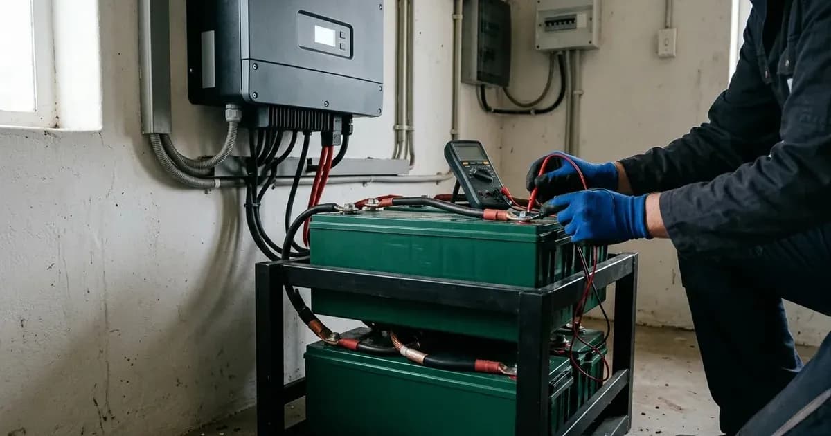
- Verify inline DC battery disconnect breakers and high-current ceramic fuses. A blown battery fuse prevents both charge current flow and DC voltage sensing. Always isolate power first and use an insulated tool to avoid short circuits. Dropping a conductive spanner across battery terminals can short hundreds of amps, leading to violent arcing, molten metal splatter, and explosive battery rupture.
Common Causes and Fixes for Tesla Inverter Battery Not Charging
Symptom & Code | Likely Hardware / Firmware Cause | Diagnostic Fix Direction |
|---|---|---|
Inverter displays Fault 03 / Warning 03 | Charging voltage overshoot or mismatched battery chemistry | Verify Program 05 chemistry selection; check Program 26 bulk (56.4 V default) and Program 27 float (54V default); reduce Program 02/11 current. |
Inverter displays Fault 04 / Warning 04 | Battery bank voltage collapsed below cutoff (21.0 V for 24V; 42.0 V for 48V) | Re-charge battery from WAPDA grid or solar PV; test specific gravity of tubular electrolyte with eye protection; check for dead/shorted cells. |
Inverter displays Fault 56 / clicking relay | Open battery circuit, tripped DC breaker, or blown fuse | Inspect battery cables and terminal lugs; close DC breaker; replace blown battery fuse. Always isolate power first and use an insulated tool to avoid short circuits. Wait at least 5 minutes after isolation for internal capacitors to discharge. User-performed internal work may void your warranty. |
No solar charging in full daylight | Array PV voltage below MPPT startup threshold (120V–130VDC on HLE 6KW; 60Vdc on 3KW) | Reconfigure PV string combinations in series to raise VOC above startup threshold; check for panel shading and clean anti-dust filter foam. |
No WAPDA grid charging during voltage drops | Grid voltage below 170V with Program 03 in UPS mode; or tripped AC protector | Switch Program 03 from |
Solar power powers load but leaves battery flat | Program 01 set to | Change Program 01 output priority to |
BMS communication lost (displayed as code 60/61 on some lithium-BMS models; not part of the standard 01–32 warning table) | BMS communication lost between battery and inverter | Inspect custom RJ45 cable pinout (PIN 3/5 RS485 at 9600 bps, or PIN 6/7 CAN); ensure Program 05 is set to |
Inverter Settings for Battery Charging (Program Reference)
The following table summarizes the key program parameters on Tesla Industries / Voltronic inverters for battery charging:
Program # | Program Name | Parameter Options | 24V Default / Setting | 48V Default / Setting | Charging & Safety Guidance |
|---|---|---|---|---|---|
Program 01 | Output source priority | | | | |
Program 02 | Maximum charging current | 10A to 120A (10A increments) | 60A (default); 20A–30A for 200Ah | 60A (default); 20A–30A for 200Ah | Configurable from 10A to 120A. For lithium, select PYL/Lib in Program 05 so charge limits auto-configure, and never exceed the battery BMS's rated charge current. |
Program 03 | AC input voltage range | | | | |
Program 05 | Battery type | | | | |
Program 11 | Maximum utility charging current | 2A, 10A, 20A, 30A, 40A, 50A, 60A, 80A, 100A | 30A (default); 15A–20A for 200Ah | 30A (default); 20A–30A for 200Ah | Controls AC charging rate from WAPDA grid. |
Program 16 | Charger source priority | | | | |
Program 26 | Bulk charging voltage (C.V voltage) | 25.0V to 31.5V (24V) / 48.0V to 61.0V (48V) | Default 28.2 V (AGM) | Default 56.4 V (AGM) | Constant voltage charging stage threshold. |
Program 27 | Floating charging voltage | 25.0V to 31.5V (24V) / 48.0V to 61.0V (48V) | Default 27V (AGM) | Default 54V (AGM) | Maintenance trickle charge voltage. |
Program 29 | Low DC cut-off voltage | 20.0V–24.0V (24V) / 40.0V–48.0V (48V) | Default 21.0 V; 22.0 V for tubular | Default 42.0 V; 44.0 V for tubular | Battery disconnect threshold to protect cells from deep sulfation. |
Program 30 | Battery equalization enable | | | | Equalization reverses stratification; drives cells into hydrogen gassing region; requires ventilated space away from sparks and flames. Mandatory |
Program 31 | Battery equalization voltage | 25.0V to 31.5V (24V) / 48.0V to 61.0V (48V) | Default 29.2 V (24V) | Default 58.4 V (48V) | Periodic equalization voltage. Must be disabled on lithium. |
Program 33 | Battery equalized time | 5min to 900min (5min increments) | Default 60min (1 hour) | Default 60min (1 hour) | Duration of constant voltage equalization phase. |
Program 34 | Battery equalized timeout | 5min to 900min (5min increments) | Default 120min (2 hours) | Default 120min (2 hours) | Extended timeout allowance to reach equalization voltage. |
Program 35 | Equalization interval | 0 to 90 days (1 day increment) | Default 30 days | Default 30 days | Frequency of automatic periodic equalization cycles. |
Solar PV Input and AC Grid Technical Considerations
Solar Array MPPT Voltage Window
For proper solar charging, string open-circuit voltage (VOC) must stay within operating boundaries:
- On single-phase Infinity HLE 6KW / Axpert VM IV models, the operational MPPT range is 120Vdc ~ 430Vdc with a maximum VOC of 500VDC. Startup voltage is 120V–130VDC.
- On 24V HLE 3KW models, the operational MPPT range is 60Vdc ~ 450Vdc with a startup voltage of 60Vdc ± 10Vdc.
- Always calculate array VOC for winter cold temperatures to avoid exceeding your model's Max VOC — 450VDC on HLE 3KW / Axpert 24V models and Infini Solar VIII, 500VDC on Infinity HLE 6KW/8KW and Axpert VM III TWIN, 550VDC on HSC 6kW, and 1000VDC only on HSC 10/12kW and Infini Plus three-phase units (Fault 59: PV voltage beyond acceptable range).
Anti-Dust Filter Kit Maintenance
Tesla inverters equipped with removable anti-dust filter kits must have the air filter foam cleaned every 1 month to prevent restricted airflow, fan strain, and Warning 10 or Fault 02 over-temperature trips (>100°C).
Safety When Troubleshooting Your Inverter
Working around high-voltage solar power electronics and energy storage systems carries severe electrical hazards:
- High-Voltage DC Shock Hazard: Solar array open-circuit voltages reach up to 500VDC on single-phase Infinity HLE / Axpert models and up to 1000VDC on HSC and three-phase Infini Plus series. High DC voltages lack natural zero-crossing points and sustain persistent, lethal electrical arcs.
- Capacitor Discharge Safety Window: Internal high-voltage DC bus capacitors retain dangerous electrical charges after shutdown. Technicians must wait at least 5 minutes after isolating PV, battery, and AC grid disconnects before removing chassis covers.
- Flooded Lead-Acid Equalization Gassing & Ventilation: During battery equalization cycles (Program 30/31 at 29.2 V / 58.4 V), flooded lead-acid and tubular batteries release flammable hydrogen and oxygen gases. Battery compartments must maintain active cross-ventilation in a space away from sparks and open flames. Never activate equalization on sealed lithium or gel batteries.
- Eye Protection & Electrolyte Handling: Always wear safety goggles and eye protection when checking specific gravity with a hydrometer or adding distilled water to flooded cells. Add water only, never acid.
- Insulated Tools & Short-Circuit Prevention: Always kill power first and use an insulated tool when tightening terminal lugs or replacing DC fuses. Dropping a conductive spanner across battery terminals shorts hundreds of amps, leading to violent arcing, molten metal splatter, and explosive battery rupture.
When to Call a Technician Instead
While setting misconfigurations (Program 16, Program 03) can be corrected via the LCD keypad, certain hardware conditions require authorized service center intervention:
- Persistent Internal Board Faults: Fault 08 (Bus voltage too high), Fault 09 (Bus soft start failed), Fault 53 (Inverter soft start failed), or Fault 57 (Current sensor failed) indicate internal component failures requiring motherboard repair.
- Blown Internal Mainboard Fuses: Opening the chassis to replace internal components risks high-voltage shock and voids the official 1-Year to 2-Year repair/replacement warranty.
- Persistent BMS Communication Lockout: If lithium battery comm faults (displayed as code 60/61 on some lithium-BMS models; not part of the standard 01–32 warning table) persist after verifying RJ45 pinout assignments and Program 05 protocols.
Tesla Industries Pvt Ltd maintains official technical service centers in Islamabad, Lahore, and Karachi. Contact authorized support via their official web portal at https://tesla-pv.com/ or helpline at +92 321 8375278.
Still showing the fault? Book a technician
If the steps above did not clear it, tell us the inverter or battery and the exact code. We pass it to a technician who covers your city; visit charges are quoted before they come.
How this pays for the site: the technician or verifier pays SolarNevs a fixed introduction fee. Nobody pays to be recommended, and you are free to use our free guides instead.
Frequently asked questions
Why is my Tesla inverter battery not charging from solar panels?
Solar charging fails if Program 16 is set to CUT (Utility first) or OSO when grid power is needed, or if array voltage drops below the MPPT startup threshold (120V–130VDC on Tesla Infinity HLE 6KW, or 60Vdc ± 10Vdc on HLE 3KW). Check for string shading, blown DC string fuses, or insufficient series panels. Open the PV DC isolator before opening any string-fuse holder — never pull a PV fuse under load; string wiring can sit at several hundred volts DC. Wait at least 5 minutes after isolation for internal capacitors to discharge. User-performed internal work may void your warranty.
What does Tesla inverter Fault 03 or Warning 03 mean?
Fault 03 indicates battery voltage exceeds high DC cut-off threshold (>63.0 V on 48V, >33.0 V on 24V), shutting down charging to protect hardware. Warning 03 sounds a beep once every second when voltage exceeds standard curves. For 48V AGM lead-acid banks, verify bulk (56.4 V) and float (54V) charging voltages (typically referenced to 25°C standard temperature). For flooded/tubular batteries, these values should be adjusted as per manufacturer recommendations and Program 05 setting.
Why is my Tesla inverter not charging from the WAPDA grid?
Grid charging disconnects if utility voltage drops below Low Loss Voltage (170Vac ± 7V in UPS mode or 90Vac ± 7V in Appliance mode Program 03), or if the AC input protector button has tripped (input displays 0V with flashing green LED). Set Program 16 to SNU (Solar and Utility) and switch Program 03 to APL (90–280VAC) for unstable Pakistani grids.
What causes Tesla inverter Fault 56 and clicking relays?
Fault 56 indicates battery connection is open or disconnected. If the internal relay switches on and off repeatedly while LCD and LEDs flash, check battery cables, tighten terminal lugs, and verify the inline DC battery breaker and fuse are intact. Always isolate power first and use an insulated tool, because a metal spanner dropped across a bank shorts hundreds of amps. Wait at least 5 minutes after isolation for internal capacitors to discharge. User-performed internal work may void your warranty.
How should I safely equalize flooded tubular batteries on a Tesla inverter?
On flooded tubular batteries, periodic equalization at 29.2 V (24V) or 58.4 V (48V) for 60min in Program 30/31 clears plate sulfation and acid stratification. Because equalization drives cells into the hydrogen gassing region, maintain active cross-ventilation in a dedicated space away from sparks and open flames. Never activate equalization on sealed lithium or gel batteries.
References
- Voltronic Power Axpert VM IV-4K6K-TWIN Off-grid Manual — accessed 24 August 2026
- Tesla Infinity HLE 6KW Hybrid Solar Inverter Product Page — accessed 24 August 2026
- Tesla HLE 3kW Hybrid Solar Inverter 24V Product Page — accessed 24 August 2026
- Tesla Industries (Pvt) Ltd Official Web Portal — accessed 24 August 2026
Related guides
More from inverter errors & fixes.