Victron Phoenix Inverter Smart 1600VA-5000VA Setup Guide
Updated 6 September 2026 · By SolarNevs Research Desk, Dealer surveys + verified sources · 2 sources · Method ↗
Key Takeaways
- Proper DC cable sizing and connection are critical to prevent premature low-voltage cut-offs and ensure safe operation.
- Use the VictronConnect app via Bluetooth for all initial configuration and fine-tuning of inverter settings.
- Always install an appropriately rated DC fuse within 1 meter of the battery's positive terminal to protect against short circuits.
- Consult a qualified electrician or Victron Energy installer if you are unsure about high-voltage DC wiring, AC connections, or system integration.
How do I set up my Victron Phoenix Inverter Smart for reliable operation?
Setting up your Victron Phoenix Inverter Smart involves careful physical installation, secure wiring, and precise configuration via the VictronConnect app. The primary goal is to ensure safe operation and optimal performance from your 1600VA to 5000VA inverter.
Initial Installation and Wiring Steps
Proper installation is fundamental for the safe and efficient operation of your Victron Phoenix Inverter Smart. Follow these steps carefully:
- Mount the Inverter: Choose a well-ventilated location, ideally indoors, away from direct sunlight, moisture, and flammable materials. The inverter features an IP21 enclosure protection rating. Ensure sufficient clearance around the unit for airflow. The operating temperature range is from -40°C to +65°C, with performance derating above 25°C. For example, a 5000VA model's continuous output at 25°C is 4000W, which reduces to 3700W at 40°C and 2800W at 65°C.
- Install DC Fuse: Before connecting any cables to the inverter, install an appropriately rated DC fuse within 1 meter of the battery's positive terminal. This fuse protects the system from short circuits and overcurrents.
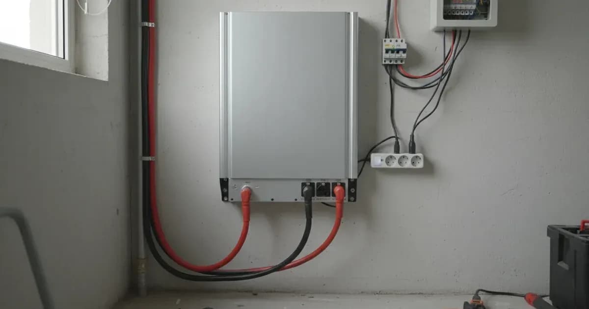
- Connect DC Cables: Use heavy-gauge, low-resistance cables for the DC connection between the battery bank and the inverter. Undersized battery cables can cause excessive voltage drop and premature low-voltage cut-offs, especially during high surge loads. The Phoenix Inverter Smart models feature M8 battery connection terminals. Tighten these M8 battery connection bolts to the manufacturer's specified torque to prevent terminal overheating and excessive DC ripple.
- Connect AC Output: Wire your AC loads to the inverter's AC output terminals. Ensure all AC wiring complies with local electrical codes. If you are integrating the inverter with other AC sources, such as a grid connection or generator, you must use an automatic transfer switch, like the Filax 2, to prevent dangerous backfeed.
- Remote On/Off (Optional): If desired, wire an external remote on/off switch or relay contact across the dedicated 2-pole connector on the main board. This allows for convenient control of the inverter without direct access.
- VE.Direct Connection (Optional): For advanced monitoring and system integration, connect a VE.Direct cable from the Phoenix Inverter Smart to a Victron Cerbo GX. This enables remote console monitoring and VRM (Victron Remote Management) telemetry.
Configuration via VictronConnect App
The VictronConnect app is the primary tool for configuring your Phoenix Inverter Smart. It connects via the inverter's integrated Bluetooth.
- Download VictronConnect: Install the VictronConnect app on your smartphone or tablet.
- Connect via Bluetooth: Open the app and scan for your Phoenix Inverter Smart. Select the device to connect. Bluetooth is built-in, making setup easier.
- Configure Basic Settings:
- Output Voltage: Adjust the AC output voltage. The configurable range is 210V to 245V AC, with a nominal output of 230VAC ± 2%.
- Output Frequency: Select either 50 Hz or 60 Hz. The frequency accuracy is ± 0.1%.
- Low DC Cut-off: Set the low DC voltage threshold at which the inverter will shut down to protect your battery. The inverter includes dynamic load-dependent low-DC shutdown.
- ECO Mode: Enable ECO mode to reduce standby power consumption. In ECO mode, the inverter wakes up for a short check period every 2.5 seconds (adjustable). Zero-load standby power is 8W to 20W depending on the model, reducing to 0.6W to 1.5W in ECO mode.
- Alarm Relay: Configure the programmable alarm relay. Its ratings are 230VAC / 4A, 4A / 35VDC, and 1A / 60VDC.
- Save Settings: After making changes, ensure you save the configuration to the inverter.
Inverter Performance and Operational Settings
Understanding the performance characteristics of your Phoenix Inverter Smart helps in optimizing its use and preventing overload conditions.
Setting/Parameter | Description | Value/Range |
|---|---|---|
Output Voltage Range | Configurable AC output voltage | 210V to 245V AC (nominal 230VAC ± 2%) |
Output Frequency | Selectable AC output frequency | 50 Hz or 60 Hz (± 0.1%) |
Peak Power Rating | Maximum instantaneous power output | 3000W (1600VA), 4000W (2000VA), 6000W (3000VA), 10000W (5000VA) |
Continuous Output at 25°C | Sustained power output at 25°C ambient | 1300W (1600VA), 1600W (2000VA), 2400W (3000VA), 4000W (5000VA) |
Continuous Output at 40°C | Sustained power output at 40°C ambient | 1200W (1600VA), 1450W (2000VA), 2200W (3000VA), 3700W (5000VA) |
Continuous Output at 65°C | Sustained power output at 65°C ambient | 800W (1600VA), 1000W (2000VA), 1700W (3000VA), 2800W (5000VA) |
Maximum Efficiency | Inverter's conversion efficiency | 92% (12V models), 94% (24V models), 95% to 96% (48V models) |
Zero-Load Standby Power | Power consumed when no load is present | 8W to 20W (normal), 0.6W to 1.5W (ECO mode) |
ECO Mode Sampling Interval | How often the inverter checks for load in ECO mode | 2.5 seconds (adjustable) |
Programmable Relay Ratings | Electrical limits for the alarm relay | 230VAC / 4A, 4A / 35VDC, 1A / 60VDC |
Operating Temperature Range | Ambient temperature limits for operation | -40°C to +65°C |
Safety: Essential Precautions
Working with inverters and battery systems involves significant electrical hazards. Adhere to these safety guidelines:
- DC Fusing: Always install an appropriately rated DC fuse within 1 meter of the battery positive terminal before connecting the inverter. This protects against catastrophic short circuits.
- Terminal Connections: Always use insulated tools and isolate the battery bank before tightening M8 battery connection bolts to manufacturer torque specifications. Loose connections can cause resistance, leading to heat buildup, voltage drops, and potential fire hazards, while accidental tool contact across terminals can cause high-current short circuits.
- Power Isolation: Before removing the terminal cover, servicing connections, or performing any maintenance, isolate both the DC battery supply and all AC output loads. Verify that no voltage is present before proceeding.
- Ventilation: Ensure the inverter is installed in a well-ventilated area. Operating in unventilated enclosures can lead to thermal derating and reduced output power.
- AC Transfer Switch: If connecting the inverter's AC output to a system with other AC sources (like grid or generator), always use an automatic transfer switch. Omitting this can cause dangerous backfeed into the grid or other sources.
When to call a technician instead
While this guide covers the essential setup steps, certain situations warrant professional assistance:
- Complex AC Wiring: If your installation involves integrating the inverter into a complex existing AC distribution board or requires new circuit installations, consult a licensed electrician.
- DC Cable Sizing Uncertainty: If you are unsure about the correct DC cable cross-section for your specific battery bank and inverter model, a professional can calculate this to prevent undersizing and performance issues.
- System Integration: For advanced setups involving multiple Victron devices (e.g., charge controllers, battery monitors, Cerbo GX) and communication protocols, an experienced Victron Energy installer can ensure proper configuration and optimal system performance.
- Persistent Faults: If the inverter displays persistent fault codes or does not operate as expected after following all setup and troubleshooting steps, contact a qualified service technician.
- Warranty Concerns: Any unauthorized modifications or improper installation may void the inverter's 5-year standard warranty. If in doubt, seek professional help.
For further integration with other Victron components, you may find these guides helpful:
Add a battery at a surveyed price
Installers quote supply and fitting of the battery on this page for your existing or new system.
How this pays for the site: installers pay SolarNevs a fixed introduction fee when we pass them a genuine enquiry. They cannot pay to appear higher, and our surveyed prices are published before any introduction. You can also take our dated price tables straight to any installer.
Frequently asked questions
What models are covered by the Victron Phoenix Inverter Smart series?
The Phoenix Inverter Smart series includes models with 1600VA, 2000VA, 3000VA, and 5000VA continuous ratings. These are available for 12V, 24V, or 48V DC battery systems.
How do I configure the Victron Phoenix Inverter Smart?
You can configure settings such as output voltage, frequency, low DC cut-off, and ECO mode using the VictronConnect app. This app connects to the inverter via its integrated Bluetooth.
What are the peak power capabilities of these inverters?
Due to their toroidal transformer architecture, these inverters offer high peak power. Ratings range from 3000W for the 1600VA model up to 10000W for the 5000VA model.
What safety precautions are essential during installation?
Always install an appropriately rated DC fuse within 1 meter of the battery's positive terminal. Tighten M8 battery connection bolts to manufacturer specifications, and isolate all power before servicing.
Can I monitor the Victron Phoenix Inverter Smart remotely?
Yes, you can connect the inverter via a VE.Direct cable to a Cerbo GX. This enables remote console monitoring and VRM telemetry for your system.
References
- Victron Energy Phoenix Inverter Smart Product Page — accessed 23 August 2026
- Victron Energy Phoenix Inverter Smart 1600VA-5000VA Datasheet — accessed 23 August 2026
Related guides
More from what to buy — and how not to get cheated.