Inverter Not Turning On: Dead Unit Diagnosis
Updated 6 September 2026 · By SolarNevs Research Desk, Dealer surveys + verified sources · 5 sources · Method ↗
Key Takeaways
- The most common cause for a dead inverter is a complete lack of power from the battery, PV, or grid.
- Always start troubleshooting by safely checking all external circuit breakers and battery connections.
- Never attempt internal repairs or open the inverter casing yourself, as this poses a severe electric shock risk and can void your warranty.
- If basic external checks do not resolve the issue, or if you suspect internal damage, contact a qualified technician.
Why is my solar inverter not turning on?
A solar inverter that shows no signs of life – no display, no lights, no fan noise – typically indicates a complete loss of power input or a critical internal failure. The most common causes are deeply discharged batteries, disconnected power sources, or tripped safety devices like circuit breakers or internal fuses.
Diagnosis
Follow these steps to diagnose why your inverter is not turning on. Always prioritize safety and disconnect power sources as instructed before proceeding with physical checks.
- Check all external breakers and switches.
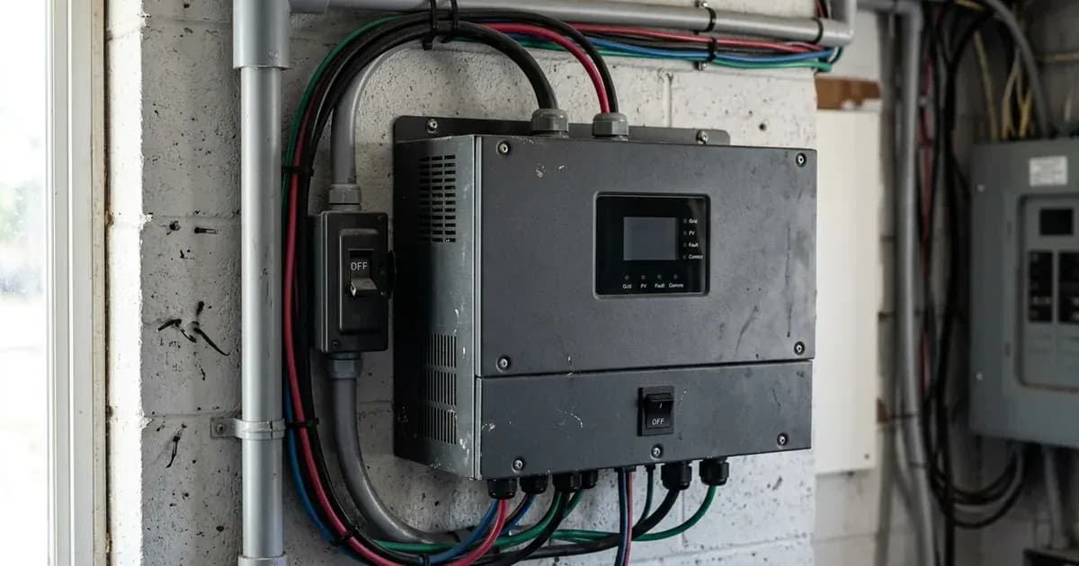
- Action: Locate and inspect all AC and DC circuit breakers connected to your inverter. This includes breakers for the grid input, AC output (loads), PV input, and battery bank. Ensure they are all in the "ON" position.
- What it means: If any breaker is tripped (often indicated by a central or "OFF" position), it has cut power to or from the inverter. Resetting a tripped breaker might restore power. If a breaker immediately trips again, there is a short circuit or overload that requires further investigation.
- Safety: Before touching any breakers, ensure you are wearing appropriate personal protective equipment, including insulated gloves.
- Verify battery voltage.
- Action: With all power sources disconnected from the inverter (AC grid, PV, and battery), use a multimeter to measure the voltage directly at your battery terminals.
- What it means: Many inverters require a minimum battery voltage to initiate startup. For example, an Axpert VM III 5KW inverter requires 46.0Vdc to cold start. A Growatt SPF 5000 ES in Lead-Acid Mode also requires 46.0Vdc. If the battery voltage is too low, the inverter will not power on. For Growatt SPF 3500 ES / SPF 5000 ES in Li Mode, a default 30% State of Charge (SOC) is required for cold start, which is 10% above the Low DC Cut-off SOC.
- Safety: Be very cautious when working with metal tools on or around batteries. A potential risk exists to drop a tool to spark or short circuit batteries or other electrical parts and could cause an explosion. Ensure positive (+) is connected to positive (+) and negative (-) to negative (-). Reverse polarity connection on a Deye inverter will damage the unit.
- Inspect battery connections.
- Action: Visually inspect the battery cables connected to your inverter. Look for loose terminals, corrosion, or signs of damage. Gently attempt to tighten any loose connections.
- What it means: Loose or corroded connections can prevent the inverter from receiving adequate power, even if the battery itself has sufficient voltage. Reversed battery polarity, as noted for Growatt SPF 3500 ES / SPF 5000 ES models, will also prevent the unit from powering on.
- Safety: Disconnect all power sources (PV, grid, battery) before tightening any connections. A spanner across a battery bank can short hundreds of amps.
- Check PV input (if applicable).
- Action: If your inverter can cold start from PV, ensure PV modules are exposed to sunlight and the PV DC switch is in the "ON" position. Measure the PV voltage at the inverter's PV input terminals (with the inverter disconnected from other power sources).
- What it means: Some inverters, like the Solis S5-EH1P-L Series, may not power on if only PV is available and the PV voltage is too low or the DC switch is off. A Deye SUN-SG03LP1-EU inverter can light up its LCD even without a battery if PV or grid is connected, showing "OFF" on the display; it can still work if the ON/OFF button is switched on and "NO battery" is selected.
- Safety: PV modules supply a DC voltage when exposed to sunlight. When installing PV modules in the daytime, cover them with opaque materials to avoid high terminal voltage.
- Examine AC input (if applicable).
- Action: If your inverter is designed to power on from the AC grid, ensure the grid supply is active and the AC input breaker is "ON".
- What it means: A lack of AC input power can prevent some inverters from starting, especially if the battery is also depleted.
Cause/fix table
Symptom detail | Likely cause | Fix |
|---|---|---|
No response after power on, no indication (Growatt SPF 3500 ES / SPF 5000 ES) | The battery voltage is far too low (<1.4V/Cell) | Recharge the battery using an external charger or allow PV to charge if possible. |
No response after power on, no indication (Growatt SPF 3500 ES / SPF 5000 ES) | Battery polarity is connected reversed. | Disconnect all power, correct battery polarity, then reconnect. |
All LED off (Solis S5-EH1P-L Series) | Inverter is not receiving any power. | Check all AC and DC breakers, battery connections, and PV input. |
All LED off (Solis S5-EH1P-L Series) | Abnormal control board functionality. | Contact a qualified technician or service center. |
All LED off (Solis S5-EH1P-L Series) | Firmware update interrupted. | Contact a qualified technician or service center. |
All LED off (Solis S5-EH1P-L Series) | LED ribbon cable came loose during transport. | Contact a qualified technician or service center. |
No response after power on, no indication (Axpert VM III) | The battery voltage is far too low (<1.4V/Cell) | Re-charge battery. If the battery is severely discharged, it may need replacement. |
No response after power on, no indication (Axpert VM III) | Internal fuse tripped. | Contact a qualified technician or service center. |
Inverter does not power on (Solis S5-EH1P-L Series) | Only PV available and PV voltage is too low or DC switch is off. | Ensure PV voltage is sufficient and the inverter DC switch is on. |
Power-On Sequence and Initial Checks
Understanding the power-on sequence and initial checks for your specific inverter model can help you identify where the startup process is failing.
Power-On Sequence
Most inverters require a specific sequence of power connections to start correctly.
- Growatt SPF 3500 ES / SPF 5000 ES: Once the unit is properly installed and batteries are connected well, simply press the On/Off switch (located on the bottom of the case) to turn on the unit.
- Solis S5-EH1P-L Series:
- Measure DC voltage of PV strings and battery, ensuring correct polarity.
- Measure AC voltage and frequency, ensuring they are within local standards.
- Switch on the external AC breaker to power on the LCD of the inverter.
- Switch on the inverter DC switch.
- Switch on the battery breaker.
- Verify readings in "Information" pages.
- Axpert VM III: Once the unit is properly installed and the batteries are connected well, simply press the On/Off switch (located on the display panel) to turn on the unit.
- Deye SUN-SG03LP1-EU: Once the unit is properly installed and the batteries are connected well, simply press the On/Off button (located on the left side of the case) to turn on the unit. Note that if no battery is connected but PV or grid is, the LCD will still light up (displaying "OFF"). The system can still work if the ON/OFF button is switched on and "NO battery" is selected.
- Fox ESS H1(G2)/AC1(G2):
- Ensure the inverter is fixed well on the wall.
- Make sure all DC and AC wirings are completed.
- Make sure the CT/meter is connected well.
- Make sure the battery is connected well.
- Make sure the external EPS contactor is connected well (if needed).
- Turn on the PV/DC switch (for hybrid only), AC breaker, EPS breaker, and battery breaker.
- Enter the settings page, default password is ‘0000’, select START / STOP and set it to start.
Minimum Battery Voltage to Power Up
A common reason for an inverter not turning on is insufficient battery voltage.
- Growatt SPF 3500 ES / SPF 5000 ES:
- Lead-Acid Mode: Cold Start Voltage is 46.0Vdc.
- Li Mode: Cold Start SOC is a default 30%, which is Low DC Cut-off SOC +10%.
- Axpert VM III:
- 1.5KW/3KW models: Cold Start Voltage is 23.0Vdc.
- 5KW model: Cold Start Voltage is 46.0Vdc.
Internal Fuse/Breaker References
While you should never open your inverter to check internal fuses, understanding that they exist is important. External breakers are your first line of defense.
- Growatt SPF 3500 ES / SPF 5000 ES: Requires a separate DC over-current protector or disconnect device between the battery and inverter. Be very cautious when working with metal tools on or around batteries. A potential risk exists to drop a tool to spark or short circuit batteries or other electrical parts and could cause an explosion. Recommended AC breaker for AC input is 40A for SPF 3500 ES and 50A for SPF 5000 ES. A separate DC circuit breaker is required between the inverter and PV modules.
- Solis S5-EH1P-L Series: DC OCPD (Over-Current Protective Device) shall be installed per local requirements. AC OCPD is required for circuits connected to the inverter. Grid OCPD ratings are 25A for 3K/3.6K models, 32A for 4.6K/5K models, and 40A for the 6K model. The battery switch must have a rated current greater than or equal to 80A for 3K~3.6K Models, and 125A for 4.6K~6K Models.
- Axpert VM III: One piece of 150A fuse is provided as over-current protection for the battery supply. Recommended AC breaker for AC input is 16A for 1.5KW, 32A for 3KW, and 50A for 5KW. A separate DC circuit breaker is required between the inverter and PV modules.
- Deye SUN-SG03LP1-EU: A separate DC over-current protector or disconnect device is required between the battery and the inverter. Be very cautious when working with metal tools on or around batteries. Dropping a tool may cause a spark or short circuit in batteries or other electrical parts, even cause an explosion. A separate AC breaker is required between the inverter and the grid. For the 3.6/5/6KW model, the recommended AC breaker for the grid is 40A, and for backup load, it is 32A/40A.
LCD Display in Each State
A truly "dead" unit will have no display. However, some inverters might show a minimal display even when not fully operational.
- Solis S5-EH1P-L Series: The initial power-on state shows a "Set Language" screen. In normal operation, the POWER LED and OPERATION LED are "ON". If the ALARM LED is "ON", it indicates a fault condition. If the ALARM LED is "FLASHING", it means grid or solar cannot be detected.
- Fox ESS H1(G2)/AC1(G2): A green LED indicates the inverter is in a normal state. A blue LED indicates the inverter is normally connected to the battery. A red LED indicates the inverter is in fault mode.
Safety
Working with solar inverters and battery systems involves significant electrical hazards. Always follow safety guidelines to prevent injury or damage.
- Disconnect all power sources: To reduce the risk of electric shock, disconnect all wirings before attempting any maintenance or cleaning. Turning off the unit alone will not reduce this risk. For Solis S5-EH1P-L Series inverters, do not touch any inner live parts until 5 minutes after disconnection from the utility grid and the PV input, due to energy stored in capacitors.
- Qualified personnel only: All operations, including installation, start-up, and maintenance, must be carried out by qualified, trained personnel. For Axpert VM III, only qualified personnel can install this device with a battery.
- Do not disassemble: Do not disassemble the unit. Take it to a qualified service center when service or repair is required. Incorrect re-assembly may result in a risk of electric shock or fire. Opening the unit may also void the warranty.
- Battery safety: Be very cautious when working with metal tools on or around batteries. Dropping a tool may cause a spark or short circuit in batteries or other electrical parts, potentially causing an explosion. Never charge a frozen battery.
- Correct polarity: Before making the final DC connection or closing a DC breaker/disconnector, be sure positive (+) must be connected to positive (+) and negative (-) must be connected to negative (-). Reverse polarity connection on a Deye inverter will damage the inverter.
- Hot surfaces: The surface temperature of a Solis S5-EH1P-L Series inverter can reach up to 75°C (167°F). To avoid risk of burns, do not touch the surface of the inverter while it is operating.
- PV module safety: PV modules supply a DC voltage when exposed to sunlight. When installing PV modules in the daytime, cover them with opaque materials to avoid high terminal voltage.
When to call a technician instead
You should call a qualified technician or your service center if:
- The inverter shows no signs of life after you have performed all external checks (breakers, battery voltage, connections).
- You suspect an internal fuse has tripped (as noted for Axpert VM III).
- The inverter indicates an internal fault, such as "Abnormal control board functionality" or "Firmware update interrupted" (Solis S5-EH1P-L Series).
- You detect reversed battery polarity and are unsure how to safely correct it.
- Any breaker immediately trips again after being reset, indicating a persistent electrical fault.
- You are uncomfortable performing any of the diagnostic steps yourself, especially those involving electrical measurements.
- Your inverter's manual explicitly states to "Return to repair center" for the observed symptom, as seen for Axpert VM III error codes 03, 08, 09, 52, 53, 55, 57, 58.
- The issue persists after following the basic troubleshooting steps. Many manuals, including those for Growatt, Deye, and Fox ESS, advise contacting their service center if a fault cannot be resolved.
- Opening the inverter casing is required for diagnosis or repair, as this is typically restricted to authorized service personnel and can void your warranty.
Still showing the fault? Book a technician
If the steps above did not clear it, tell us the inverter or battery and the exact code. We pass it to a technician who covers your city; visit charges are quoted before they come.
How this pays for the site: the technician or verifier pays SolarNevs a fixed introduction fee. Nobody pays to be recommended, and you are free to use our free guides instead.
Frequently asked questions
What is the minimum battery voltage for a Growatt SPF 5000 ES to cold start?
The Growatt SPF 5000 ES requires a minimum cold start voltage of 46.0Vdc in Lead-Acid Mode. For Lithium batteries, it requires a default 30% State of Charge (SOC), which is 10% above the Low DC Cut-off SOC.
What should I check if my Solis S5-EH1P-L Series inverter has no LEDs on?
If all LEDs are off on a Solis S5-EH1P-L Series inverter, check for abnormal control board functionality, an interrupted firmware update, or a loose LED ribbon cable during transport. Also, ensure the inverter is receiving power.
Can a reversed battery polarity prevent an inverter from turning on?
Yes, for models like the Growatt SPF 3500 ES / SPF 5000 ES, reversed battery polarity can cause the inverter to show no response or indication after power on.
What is the cold start voltage for an Axpert VM III 5KW inverter?
The Axpert VM III 5KW inverter has a cold start voltage of 46.0Vdc.
What is the recommended AC breaker size for a Growatt SPF 5000 ES inverter?
For a single Growatt SPF 5000 ES inverter, the recommended AC breaker size for the AC input power source is 50A.
References
- Growatt SPF 3500 ES / SPF 5000 ES Manual — accessed 23 August 2026
- Solis S5-EH1P-L Series Manual — accessed 23 August 2026
- Axpert VM III Manual — accessed 23 August 2026
- Deye SUN-3.6_6K_SG03LP1_EU Manual — accessed 23 August 2026
- Fox ESS H1(G2)/AC1(G2) Manual — accessed 23 August 2026
Related guides
More from inverter errors & fixes.