Solar Panel Hot Spot: Causes, Diagnosis, and Fixes
Updated 7 September 2026 · By SolarNevs Research Desk, Dealer surveys + verified sources · 5 sources · Method ↗
Key Takeaways
- Solar panel hot spots are localized areas of high temperature, often caused by shading, internal cell damage, or bypass diode failure.
- The first step in diagnosis is a visual inspection for external shading or physical damage, followed by infrared (IR) imaging.
- Never attempt to clean a PV module with broken glass or exposed wiring, as this presents a shock hazard.
- If you detect temperature gradients above 20 °C or suspect internal electrical faults, call a qualified technician.
What causes hot spots on solar panels?
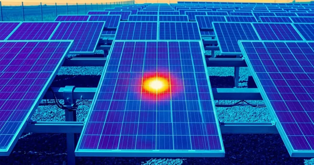
Hot spots are localized areas of high temperature on a solar panel. They occur when a section of the module, such as a single cell or a string of cells, becomes inactive or has increased resistance. When this happens, the energy from sunlight is not converted into DC power in that area. Instead, it remains as excess heat, causing the temperature of that specific part of the module to rise significantly.
Common causes of hot spots include:
- External shading: Obstructions like leaves, dirt, bird droppings, or nearby structures can partially shade cells, making them inactive.
- Internal cell problems: This includes manufacturing defects, microcracks within the cells, or shunted cells. Microcracks, often invisible to the naked eye, can restrict current flow and lead to localized heating.
- Bypass diode failures: Bypass diodes are designed to protect cells from hot spots caused by shading or damage. If a bypass diode fails, it can no longer protect its cell string, leading to overheating.
- Poor electrical connections: Loose or corroded connections within the module or junction box can increase resistance and generate heat.
- Broken front glazing: Damage to the front glass can expose cells and lead to internal cell damage, which can then cause hot spots.
Diagnosis and Troubleshooting Steps
Diagnosing hot spots requires careful observation and specialized tools. Follow these steps to identify the source of the problem.
- Visual Inspection:
- Check for external shading: Look for any leaves, dirt, bird droppings, or other debris on the panel surface. Also, observe if nearby trees, buildings, or antennas cast shadows on the panel during different times of the day.
- Inspect for physical damage: Look for visible cracks in the glass, discoloration, or burn marks on the module surface or around the junction box. Broken front glazing can cause hot spots and presents an electrical safety hazard.
- Examine connections: Carefully inspect the wiring and connectors for any signs of corrosion, looseness, or damage. Ensure all connections are secure.
- Infrared (IR) Imaging:
- Use an IR camera: An infrared camera is the most effective tool for detecting hot spots. It visualizes temperature differences across the module surface. Inactive areas of a module or string usually appear hotter than surrounding active areas.
- Optimal conditions for IR imaging: For most practical cases, an irradiance of 600 W/m² is enough to detect failures in PV modules with inactive module parts. It is recommended to use weather conditions which lead to temperature differences (ΔT) higher than 2.5 K.
- Interpret results: A temperature gradient of a single solar cell smaller than 10 °C is normally considered as unproblematic. However, temperature gradients above 20 °C are expected to cause degradations of panel output and can lead to safety issues.
- Multimeter Testing (for Bypass Diodes):
- Isolate the module: Before performing any electrical tests, ensure the module is completely disconnected from the system and covered to prevent power generation.
- Measure Open Circuit Voltage (Voc): A significant drop in the module's Open Circuit Voltage (Voc) can indicate a short-circuited bypass diode. Diode failures in short circuit often result in a loss of one-third of the module’s voltage in open circuit (Voc).
- I-V Curve Tracing: For open-circuit bypass diode failures, which are harder to detect, I-V tracing under partial shading or specialized equipment such as a diode checker is necessary.
Cause and Fix Table
Symptom detail | Likely cause | Fix |
|---|---|---|
Localized hot area on panel surface | External shading (leaves, dirt, bird droroppings) | Remove obstruction. Regular cleaning can prevent recurrence. |
Hot area on panel, no external shading, no visible damage | Internal cell problem (e.g., microcrack, shunted cell) | If severe (ΔT > 20 °C), replace the module. Microcracks are often not visible to the eye. |
Hot junction box or specific diode | Failed bypass diode (open circuit or short circuit) | Replace the module or the junction box if it is designed for field replacement. A permanent activated bypass diode leads to minimized power output. |
Reduced module voltage (Voc) by approximately one-third | Short-circuited bypass diode | Replace the module or the junction box. This failure mode results in a one-third power loss for the module. |
Broken front glass | Physical impact or stress | Remove and replace the module immediately. Never attempt to repair broken glass. |
Discoloration or burn marks on module | Severe hot spot leading to material degradation | Replace the module. This indicates long-term or extreme overheating. |
Understanding Hot Spots and Bypass Diodes
Hot spots are a critical issue for solar panel performance and safety. When a cell or a group of cells becomes inactive, perhaps due to shading or internal damage, it acts as a resistor in the circuit. The current from the active cells is forced through this resistive, inactive area, leading to significant heat generation. This localized heating can accelerate material degradation, reduce power output, and, in extreme cases, lead to smouldering fires.
Jinko Solar modules, for example, contain factory-installed bypass diodes within their junction boxes. These diodes are connected in parallel with each cell string. Their purpose is to allow current to flow around a shaded or damaged cell string, preventing it from acting as a resistor and causing a hot spot. This helps maintain performance and prevents heating losses.
Bypass diodes can fail in two primary modes:
- Short-circuit failure: When a bypass diode fails in short circuit, it effectively shorts out the sub-string of cells it is protecting. This leads to a loss of power from that section, typically resulting in a one-third power loss for the module. This type of failure is relatively easier to detect, as it causes a noticeable drop in the module's open circuit voltage (Voc) and can be identified with a multimeter, infrared imaging (showing the bypassed string as cooler than active strings), or electroluminescence imaging (where the entire sub-string appears dark).
- Open-circuit failure: If a bypass diode fails in an open-circuit state, it means the diode no longer provides a path for current to bypass the shaded or damaged cells. This condition is similar to not having the diode at all. Open-circuit failures are considered safety risks because the affected cells can then overheat and create severe hot spots. These failures are harder to detect, as they only impact module performance under shading. Specialized equipment like I-V tracers or diode checkers are often needed.
A permanent activated bypass diode, whether due to a short-circuit failure or persistent shading, leads to a minimized power output of the affected solar cell string and thus a reduction of the total power output of the plant. Modules with active bypass diodes should be substituted to restore full performance and prevent further degradation or safety issues.
Safety
Working with solar panels involves significant electrical hazards. Always prioritize safety.
- Electrical Shock and Burns: Modules generate DC electrical energy when exposed to sunlight or other light sources. Improper contact with live parts, such as terminals, may result in burns, sparks, and lethal shock.
- Disconnect Power: To prevent arcs and electrical shocks, do not disconnect modules under load without authorization. If disconnecting the connector is needed, turn off DC and AC inverters or cut off the main switch of the converter first.
- Stop Power Generation: PV module operation can only be stopped when they are kept from sunlight or covered by hard board (opaque material) or UV-proof materials.
- Work in Dry Conditions: Due to the risk of electrical shock, do not perform any work if the terminals of the module are wet. Do not operate on wet modules; if this is needed, only do so by wearing appropriate Personal Protective Equipment (PPE).
- Avoid Touching Hot Surfaces: Do not touch the module, junction box, or the connectors with bare hands during installation or under sunlight, regardless of whether the module is connected or disconnected from the system. The glass surface and the frame may be hot, posing a risk of burns and electric shock.
- No Metal Objects: Do not insert any metal object into the connector.
- Fire Safety: Do not install the modules anywhere close to open flames or flammable materials (hay, straw, wood, solvents, oils, etc.), or exposed to flammable and explosive gases.
- Damaged Modules: Never attempt to clean a PV module with broken glass or other signs of exposed wiring, as this presents a shock hazard. Breakage, opening the module to the exterior, of the front or rear glass can cause an electrical safety hazard, electric shock, or fire. These modules cannot be repaired and must be removed and replaced immediately.
When to call a technician instead
While some hot spot causes like external shading can be addressed by the system owner, many require professional intervention. You should call a qualified solar technician if:
- You observe broken glass on any part of the module. This is a severe safety hazard and the module must be removed and replaced immediately.
- Infrared imaging reveals temperature gradients above 20 °C, indicating a significant internal issue.
- You suspect a bypass diode failure (either short-circuit or open-circuit) and lack the specialized tools or expertise to diagnose it safely.
- There are signs of discoloration or burn marks on the module or junction box, which suggest severe overheating and potential fire risk.
- You are unsure about the cause of the hot spot or how to safely proceed with troubleshooting or repair.
- The issue might void your module's warranty if not handled by an authorized professional.
Still showing the fault? Book a technician
If the steps above did not clear it, tell us the inverter or battery and the exact code. We pass it to a technician who covers your city; visit charges are quoted before they come.
How this pays for the site: the technician or verifier pays SolarNevs a fixed introduction fee. Nobody pays to be recommended, and you are free to use our free guides instead.
Frequently asked questions
What causes hot spots on solar panels?
Hot spots are localized areas of high temperature on a solar panel. They are often caused by inactive cells due to external shading, internal cell problems like microcracks, or failures in the bypass diodes.
How can I detect hot spots on my solar panels?
Hot spots can be detected visually if severe, but are best identified using an infrared (IR) camera. IR imaging can reveal temperature differences, with inactive areas appearing hotter than surrounding active areas.
Are hot spots on solar panels dangerous?
Yes, hot spots can be dangerous. They can lead to significant performance degradation, accelerate material degradation, and in extreme cases, cause smouldering fires or create safety issues during maintenance work.
Can hot spots on solar panels be fixed?
The fix depends on the cause. Removing external shading is a simple fix. For internal cell problems or failed bypass diodes, the module or its junction box may need replacement. Never attempt repairs on broken glass.
What temperature difference indicates a hot spot?
A temperature gradient of a single solar cell smaller than 10 °C is normally considered unproblematic. Temperature gradients above 20 °C are expected to cause degradations of panel output and potential safety issues.
References
- JinkoSolar Global Installation Manual_20240814_A1.pdf — accessed 23 August 2026
- Review_on_IR_and_EL_Imaging_for_PV_Field_Applications_by_Task_13.pdf — accessed 23 August 2026
- pv-bypass-diode-faults-current-testing-and-scope-for-future-test-development.pdf — accessed 23 August 2026
- PVEL-White-Paper_Mechancial-Stress-Sequence_Cracking-Down-on-PV-Module-Design.pdf — accessed 23 August 2026
- PVEL Scorecard Failures — accessed 23 August 2026
Related guides
More from inverter errors & fixes.