Victron MultiPlus II GX Energy Storage System ESS Setup Guide
Updated 15 September 2026 · By SolarNevs Research Desk, Dealer surveys + verified sources · 1 source · Method ↗
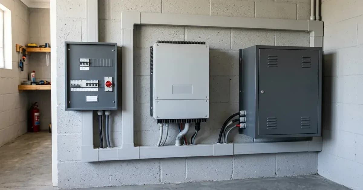
Key Takeaways
- The MultiPlus-II GX integrates a GX device, enabling Energy Storage System (ESS) functionality.
- Correct installation and orientation of Current Transformer (CT) clamps are critical for accurate grid interaction.
- CAN-Bus BMS closed-loop integration requires shielded twisted-pair cabling and correct RS485 baud rate settings.
- VE.Bus termination dip-switches must be set correctly when external GX devices or MK3-USB adapters are used.
Setting up your Victron MultiPlus-II GX for Energy Storage System (ESS)
The Victron MultiPlus-II GX is an inverter/charger designed for Energy Storage Systems (ESS), integrating a GX communication device directly into the unit. This guide details the essential steps for configuring your MultiPlus-II GX for ESS operation, ensuring compliance and optimal performance within your Great British electrical system.
How the MultiPlus-II GX ESS Architecture Works
The MultiPlus-II GX is engineered for residential and commercial off-grid and grid-parallel energy storage systems. Its integrated GX device allows it to comply with international microgeneration safety and grid protection standards. The ESS assistant dynamically manages battery charge and discharge based on grid tariffs and load, optimising energy flow. This system also features PowerControl and PowerAssist capability, allowing it to supplement grid power with battery power during peak demand or when the grid connection is limited.
Configuring CAN-Bus BMS and VE.Bus Termination
For battery systems with a CAN-Bus Battery Management System (BMS), the MultiPlus-II GX supports closed-loop integration. This ensures the inverter communicates directly with the battery's BMS for optimal charging and discharging parameters. To maintain reliable communication, you must maintain shielded twisted-pair cabling and verify proper RS485 communication baud rate settings.
Interface / Component | Configuration Requirement | Operational Purpose |
|---|---|---|
Integrated GX Controller | ESS Assistant configuration | Dynamic tariff and battery charge/discharge management |
CAN-Bus BMS Port | Shielded twisted-pair cabling | Closed-loop battery telemetry and charge parameter sync |
VE.Bus Interface | Onboard termination dip-switches set correctly | Prevents communication signal errors with external GX / MK3-USB |
Current Transformer (CT) | Arrow pointing towards household loads | Grid import/export measurement without inverted readings |
Chassis Earthing | Bonded to Main Earthing Terminal (MET) | Fault current diversion and shock protection |
Additionally, when utilising external GX devices or MK3-USB adapters, ensure the onboard VE.Bus termination dip-switches are set correctly. Incorrect termination can lead to communication errors and system instability.
Correct Current Transformer (CT) Clamp Installation
Accurate measurement of household consumption and grid interaction is vital for ESS functionality. The MultiPlus-II GX uses Current Transformer (CT) clamps for this purpose. Install Current Transformer clamps with arrows pointing towards the household loads away from the grid incomer. Incorrect orientation can lead to negative power flow readings during high household consumption, indicating an inverted CT clamp installation. This will cause the system to misinterpret energy flows, potentially leading to incorrect battery charging or discharging behaviour.
Safety and Earthing Requirements
Electrical safety is paramount during installation. It is critical to bond the inverter chassis ground and battery metal enclosure to the main installation earthing terminal. This provides a safe path for fault currents and protects against electrical shock. Before installing CT clamps on live busbars, ensure complete AC circuit isolation and lock-out. This prevents accidental contact with live components.
What you can check yourself, and what you cannot
You can verify the physical installation of CT clamps, ensuring their arrows point correctly towards household loads. You can also check the physical connections of CAN-Bus cabling and confirm the settings of VE.Bus termination dip-switches if you are following a manufacturer's guide. However, any internal wiring, component replacement, or modification of grid-protection settings must be performed by an accredited installer. Opening the unit or attempting to change grid-protection settings yourself can breach your connection agreement and compromise safety.
What the published sources do not tell you
While the MultiPlus-II GX is compatible with standard single-phase and three-phase electrical distribution systems globally, specific grid connection requirements and export limits can vary significantly between Distribution Network Operators (grid operators) in Great Britain. These grid operator-specific rules are often not detailed in general product documentation. Furthermore, while an MCS Certificate is required to access export tariffs and verify building regulations compliance, the specific tariff rates offered by energy suppliers are not set by Ofgem or Victron; these are determined by individual SEG Licensees. Always consult your grid operator for connection requirements and your chosen energy supplier for current Smart Export Guarantee (SEG) tariff details.
Still showing the fault? Book a technician
If the steps above did not clear it, tell us the inverter or battery and the exact code. We pass it to a technician who covers your city; visit charges are quoted before they come.
How this pays for the site: the technician or verifier pays SolarNevs a fixed introduction fee. Nobody pays to be recommended, and you are free to use our free guides instead.
Frequently asked questions
What are the primary technical requirements for victron multiplus ii gx energy storage system ess setup guide?
Key requirements include compliance with local grid codes, correct equipment certification, and proper electrical isolation.
Who is authorized to install and inspect victron multiplus ii gx energy storage system ess setup guide?
All high-voltage DC, AC grid tie-in, and switchboard modifications must be performed by a qualified, accredited electrical professional.
How is export power limited in victron multiplus ii gx energy storage system ess setup guide?
Export limiting is achieved using certified bidirectional smart meters or power sensors providing dynamic feedback to the inverter system.
References
- Victron Energy MultiPlus-II GX manual, rev 13 (07/2026) - installation, ESS, BMS-Can and VE.Bus (PDF) — accessed 15 September 2026
Related guides
More from inverter errors & fixes.