Solar DC Isolator Faults, Overheating, and Melting: UK Triage Guide
Updated 18 September 2026 · By SolarNevs Research Desk, Dealer surveys + verified sources · 2 sources · Method ↗
Key Takeaways
- DC isolators present the single greatest fire risk component in UK rooftop solar installations, accounting for approximately 30% of recorded incidents in official government investigations.
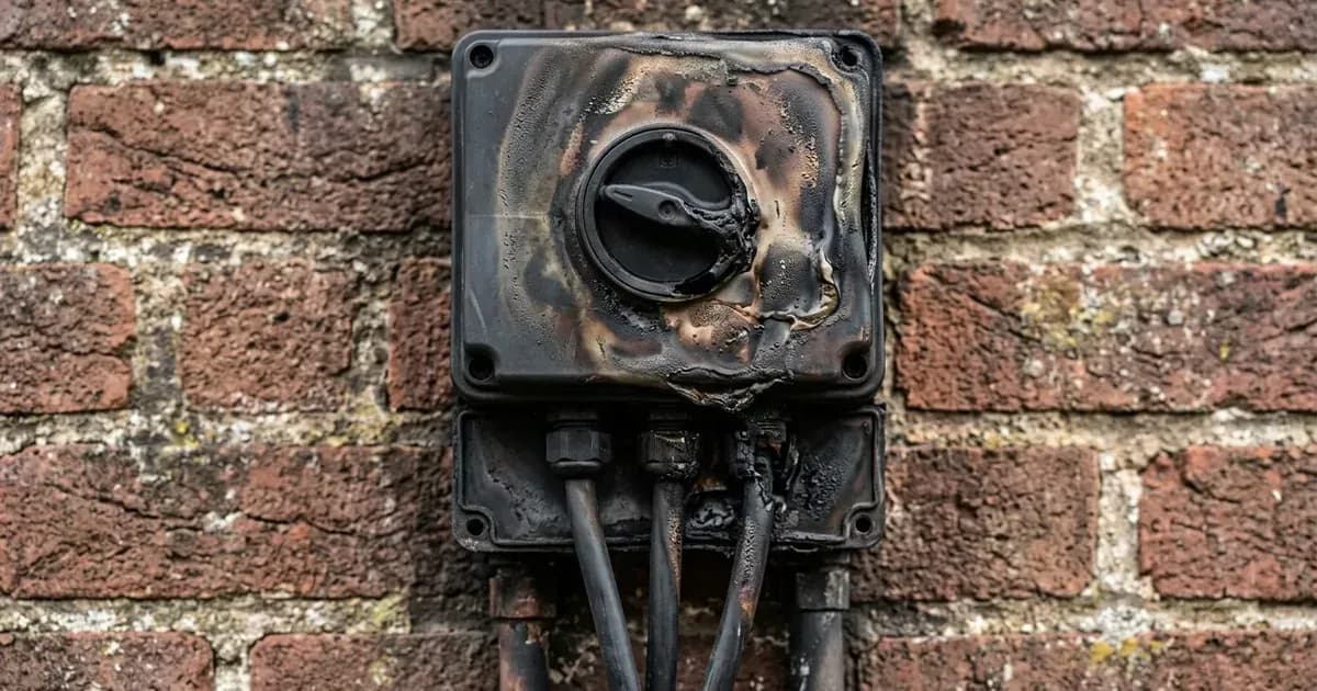
- Never operate or turn off a DC isolator that is actively buzzing, smoking, or discolored; opening a damaged switch under full solar generation can draw a lethal, sustained DC electrical arc.
- Upward-facing cable entry glands are a primary failure vector, allowing rainwater to track down cables into the enclosure and corrode internal switch contacts.
- The safe immediate response is to isolate the AC supply at your domestic consumer unit, leaving the DC side undisturbed until a qualified solar electrician arrives with protective equipment.
What is a solar DC isolator and why does it fail?
A solar direct-current (DC) isolator is a heavy-duty rotary switch installed between your rooftop solar panels and the inverter. Its purpose is to allow technicians to mechanically disconnect the high-voltage solar array for maintenance or emergency repairs.
However, forensic research conducted by the Building Research Establishment (BRE Global) revealed that DC isolators were found to present the greatest fire risk within the database of incidents. Across the forensic database, approximately 30% of the incidents recorded in this study were caused by malfunctions within this component.
With nearly 940,000 PV systems now installed in the UK and overall UK solar PV capacity stood at approximately 12.75 GW, understanding how and why these switches degrade is essential for homeowner safety. Solar strings operate at high direct-current voltages, often reaching up to 580VDC on modern residential systems. Unlike alternating current, DC electricity does not naturally cross zero volts. If contact resistance develops within the switch, current continues to flow across microscopic gaps, generating intense localized heat exceeding several hundred degrees Celsius.
Primary failure mechanisms identified in UK installations
The BRE forensic investigation categorized DC switch failures into distinct root causes:
1. Water ingress through upward-facing cable entries
Poor installation geometry is a leading contributor to catastrophic switch failure. The BRE reported that across all the incidents reviewed, 7 incidents involved ingress of water into DC isolators, all with upward-facing cable glands. When installers bring cables through the top of an outdoor-rated enclosure rather than the bottom, rainwater pools on the gland seals, eventually penetrating the casing, corroding the spring mechanisms, and causing conductive tracking between poles.
2. Substandard or re-badged AC switchgear
Early in the UK solar feed-in tariff boom, certain manufacturers supplied isolators that were fundamentally unsuited for high-voltage direct current. The BRE found evidence of fires originating within DC isolators with poor contact design (originally being designed for AC operation and being re-designated as DC-rated by the manufacturer) and with incorrect internal wiring. In its structural breakdown, category 1) Poorly designed or constructed products noted that contact design is particularly important for DC isolators, concluding that models originally designed for AC are unlikely to be reliable over the life of a PV system.
3. Undersized ratings and poor installation practices
Switches must be rated to handle the full open-circuit voltage and short-circuit current of the connected array. In category 2) Incorrectly specified DC isolators – there were 2 instances of this type of fault (PVF0037 and PVF0049) where isolators were under-rated for the current or voltage of the PV strings connected. Furthermore, category 3) Poor installation practice accounted for 9 instances of poorly installed DC isolators, representing the majority of failures leading to thermal events.
Failure Category | Investigation Evidence | Root Mechanism |
|---|---|---|
Greatest fire risk component | Approximately 30% of investigated incidents | "Approximately 30% of the incidents recorded in this study were caused by malfunctions within this component." https://assets.publishing.service.gov.uk/media/5c90a30840f0b633ff9a3537/Fires_and_solar_PV_systems-Investigations_Evidence_Issue_2.9.pdf |
Water ingress via top glands | 7 incidents reviewed with upward-facing glands | "Across all the incidents reviewed, 7 incidents involved ingress of water into DC isolators, all with upward-facing cable glands." https://assets.publishing.service.gov.uk/media/5c90a30840f0b633ff9a3537/Fires_and_solar_PV_systems-Investigations_Evidence_Issue_2.9.pdf |
AC contacts re-badged for DC | Category 1 product design defects | "1) Poorly designed or constructed products - The contact design is particularly important for DC isolators. Models that were originally designed for AC are unlikely to be reliable over the life of a PV system." https://assets.publishing.service.gov.uk/media/5c90a30840f0b633ff9a3537/Fires_and_solar_PV_systems-Investigations_Evidence_Issue_2.9.pdf |
Incorrect electrical rating | Category 2 rating shortfalls (2 instances) | "2) Incorrectly specified DC isolators – there were 2 instances of this type of fault (PVF0037 and PVF0049). In both cases, the isolators were under-rated for the current or voltage of the PV strings connected." https://assets.publishing.service.gov.uk/media/5c90a30840f0b633ff9a3537/Fires_and_solar_PV_systems-Investigations_Evidence_Issue_2.9.pdf |
Substandard installation practice | Category 3 workmanship issues (9 instances) | "3) Poor installation practice - 9 instances of poorly installed DC isolators were identified. This category therefore accounts for the majority of DC isolator failures leading to fires or thermal events." https://assets.publishing.service.gov.uk/media/5c90a30840f0b633ff9a3537/Fires_and_solar_PV_systems-Investigations_Evidence_Issue_2.9.pdf |
DC connector failures | Second most common fire source component | "The second PV component most likely to be implicated as the cause of a fire is the DC connector: in 5 cases, the connectors were most likely the source of the fire, in a further 7 cases, they may have been the source." https://assets.publishing.service.gov.uk/media/5c90a30840f0b633ff9a3537/Fires_and_solar_PV_systems-Investigations_Evidence_Issue_2.9.pdf |
Secondary failure point: DC cable connectors
Beyond rotary switch enclosures, the BRE report highlighted DC string connectors as a critical vulnerability. The investigation documented that the second PV component most likely to be implicated as the cause of a fire is the DC connector: in 5 cases, the connectors were most likely the source of the fire, in a further 7 cases, they may have been the source.
As illustrated in Figure 11 shows a typical ‘MC4’-type DC connector – these are almost universally used on UK PV installations at this point in time. When installers mix and match different brands of MC4 connectors (cross-mating) or use hand pliers rather than calibrated ratchet crimping tools, internal contact pressure is compromised, generating high-resistance micro-gaps that melt the plastic housing.
Observable warning signs of DC isolator degradation
Homeowners should inspect the exterior of their solar switchgear periodically for early indicators of thermal distress:
- Discoloration and blistering: Yellowing, browning, or warping around the rotary switch handle or screw plugs indicates intense internal heat.
- Audible sizzling or buzzing: A faint crackling or frying sound when the system generates high power indicates internal micro-arcing.
- Pungent electrical burning smell: Acrid, fishy, or sweet burning plastic odours near the inverter or loft space.
- Moisture or condensation inside the clear casing: Water droplets inside an IP65 enclosure demonstrate that environmental seals or cable glands have failed.
Emergency safety protocol: what to do if an isolator is failing
Follow these safety instructions if you detect any sign of thermal overheating:
- DO NOT TOUCH THE DC ISOLATOR HANDLE. If contact contacts are already degraded, manually turning the handle can draw a massive arc flash across opening contacts, resulting in severe burns, explosion, or blindness.
- Isolate the AC generation circuit first: Go to your domestic consumer unit and switch OFF the solar generation miniature circuit breaker or RCBO. This cuts off inverter grid synchronization and shuts down current draw through the DC switch.
- Keep clear of the enclosure: Clear flammable materials from beneath the switch enclosure and evacuate children and pets from the room.
- Call for emergency assistance: If open flames, heavy smoke, or active sparking occur, call 999 immediately and notify the fire service that a live DC photovoltaic installation is involved.
Remediation and professional replacement standards
When an accredited technician assesses a degraded DC isolator, remedial work must adhere to BS 7671 Section 712:
- Replacement with genuine DC-PV2 rated switchgear: Replacement isolators must comply with IEC 60947-3 utilization category DC-PV2, featuring knife-blade contacts with rapid spring-assisted snap-action opening.
- Bottom-entry cable glands with drip loops: All DC cables must enter the enclosure through the bottom face with IP68 compression glands and downward drip loops to prevent water migration.
- Thermal imaging verification: Following replacement, the technician must conduct radiometric thermal imaging under load to ensure all terminal screws tightened to manufacturer torque specifications exhibit zero thermal delta.
Frequently asked questions
What should I do if my solar DC isolator is hot or smells of burning plastic?
Do not touch or attempt to switch the DC isolator if it is melting, buzzing, or emitting smoke, as operating a degraded switch under load can trigger an explosive DC arc flash. Turn off the AC generation breaker at your consumer unit and immediately contact an MCS-certified solar electrician.
Why do solar DC isolators overheat and catch fire?
Unlike AC electricity which crosses zero volts one hundred times per second, direct current maintains continuous high voltage. Loose internal screw terminals, water ingress from upward-facing glands, or using AC-rated switches on DC strings cause high contact resistance and sustained electrical arcing.
Are DC isolators mandatory on UK solar PV installations under BS 7671?
BS 7671 Section 712 requires a method of DC isolation adjacent to the inverter for maintenance. While early installations often placed an external rotary isolator beside the inverter, many modern inverters integrate an internal DC switch complying with product safety standards.
What are the most common solar components to fail according to UK fire data?
Official Building Research Establishment research found that DC isolators were responsible for approximately 30% of investigated solar fire incidents, followed by cross-mated or poorly crimped DC connectors.
References
- BRE National Solar Centre: Fires and Solar PV Systems Investigations Report — accessed 29 August 2026
- GivEnergy Commissioning Portal Fault Clearing Matrix — accessed 29 August 2026
Related guides
More from inverter errors & fixes.