Solar Immersion Diverter Not Heating Water: UK Diagnostic and Fix Guide
Updated 18 September 2026 · By SolarNevs Research Desk, Dealer surveys + verified sources · 2 sources · Method ↗
Key Takeaways
- A Current Transformer (CT) Clamp is a sensor that allows the inverter to detect current passing through a cable and which direction this current is flowing, acting as the critical feedback sensor for solar hot water diversion.
- The clamp should be clipped onto the live tail coming from the property meter and the arrow should be pointing towards the inverter, ensuring correct export vector detection.
- When installing alongside battery storage or EV chargers, a clearance of up to 50-100cm may be required between adjacent CT clamps to prevent electromagnetic cross-talk.
- Diverter heating failures typically stem from reversed CT clamp polarity, mechanical tank thermostat high-limit trips, or hybrid battery charging taking priority.
- Electrical safety warning: Hot water cylinders and immersion heater elements operate on mains alternating current; never remove the plastic immersion terminal cover without isolating the dedicated circuit breaker in your consumer unit.
1. How solar immersion diverters operate
Solar immersion diverters (such as the myenergi eddi, Marlec Solar iBoost+, and Solic 200) heat domestic hot water by capturing surplus electricity that would otherwise export to the national grid. Instead of exporting power, solid-state triacs modulate power into the domestic immersion heater element.
The entire control loop depends upon precise current sensing at the incoming service intake. A Current Transformer (CT) Clamp is a sensor that allows the inverter to detect current passing through a cable and which direction this current is flowing. When excess generation begins flowing outward towards the street main, the sensor signals the diverter to throttle power into the water tank.
However, if sensor alignment or cylinder safety devices malfunction, Interference on the CT clamp can cause no/incorrect readings and electricity may be imported/exported when it has not been set to do so. In this state, the immersion element remains unpowered or draws expensive peak electricity.
2. Diagnosing CT clamp placement and orientation errors
The single most common installation failure on UK solar diverters is incorrect positioning of the Current Transformer clamp around the domestic meter tails.
Physical Orientation and Meter Tail Placement
Under installation standards, The clamp should be clipped onto the live tail coming from the property meter and the arrow should be pointing towards the inverter. If the clamp is clipped around the neutral cable, or if it encloses both live and neutral conductors simultaneously, the opposing magnetic fields cancel out, resulting in zero current measurement.
Checking Sensor Polarity
You can verify the sensor orientation directly: Checking CT Clamp Direction You can check the CT polarity is correct on the inverter screen or diverter LCD. When no heavy domestic loads are operating and solar is generating strongly, the indicated grid power must read as positive export. If turning on a domestic kettle causes the reading to become positive export while bright sunshine shows import, the clamp is installed backwards and must be reversed.
Cable Extension Specifications
In many UK homes, the electrical intake meter cupboard is situated away from the cylinder airing cupboard. According to manufacturer guidelines, The cable length between the inverter and the CT clamp should ideally be no more than 10 meters, although in some circumstances this can be extended up to 15 meters.
When extending sensor wiring, To extend the CT tails the cable used must be made of copper and an equal thickness or thicker to the existing CT cables. Using unshielded thin cabling introduces resistance and induced noise, corrupting the delicate millivolt signal.
Dual-CT Interference in Modern Homes
As UK households adopt heat pumps, EV chargers, and home batteries, multiple current transformers are often clamped onto the same incoming service tail. Installation instructions warn: When installing on a property that has other CTs being used by other devices there should be clearance from these to avoid interference. Depending on circumstances this may only need to be a small distance but a clearance of up to 50-100cm may be required. Bunching clamps directly against one another causes magnetic distortion, leading to nuisance tripping and erratic power modulation.
Installation Parameter | Engineering Specification | Source Document |
|---|---|---|
CT Sensor Operating Role | A Current Transformer (CT) Clamp is a sensor that allows the inverter to detect current passing through a cable and which direction this current is flowing. | Sunsynk CT Guide |
Orientation Arrow Rule | The clamp should be clipped onto the live tail coming from the property meter and the arrow should be pointing towards the inverter. | Sunsynk CT Guide |
Inter-Clamp Clearance | a clearance of up to 50-100cm may be required. | Sunsynk CT Guide |
Primary Extension Limit | The cable length between the inverter and the CT clamp should ideally be no more than 10 meters, although in some circumstances this can be extended up to 15 meters. | Sunsynk CT Guide |
Conductor Material Mandate | To extend the CT tails the cable used must be made of copper and an equal thickness or thicker to the existing CT cables. | Sunsynk CT Guide |
Standard Metrology Ratio | CT r atio = 100A/0.05A CT Ratio = 2000:1 | Sunsynk CT Guide |
Commercial Ratio Multiplier | CT ratio = (300A/5A) *100 CT ratio = 6000:1 | Sunsynk CT Guide |
3. Sensor ratios and hybrid battery priority interaction
Different sized inverters will have a different CT clamp rating supplied. For standard single-phase residential units, the factory calibration assumes CT r atio = 100A/0.05A CT Ratio = 2000:1. On three-phase commercial sites using larger sensors, CT ratio = (300A/5A) *100 CT ratio = 6000:1. If the diverter firmware ratio does not match the physical clamp rating, power calculations will be wrong by an order of magnitude.
Furthermore, if your home features a hybrid solar battery, the battery system almost universally takes precedence over hot water diversion. In residential inverters, Charge/Discharge Amps: The Max battery charge/discharge current (0-90A for 3.6kW model, 0-120A for 5kW model). Until the battery finishes bulk charging, zero export reaches the meter tail. Similarly, if battery reserve drops to the Shutdown 20%: It indicates the inverter will shutdown if the SOC is below this value threshold, solar generation will prioritize pack recovery before any energy is diverted to heating water.
4. Mechanical cylinder thermostat and thermal cutout reset
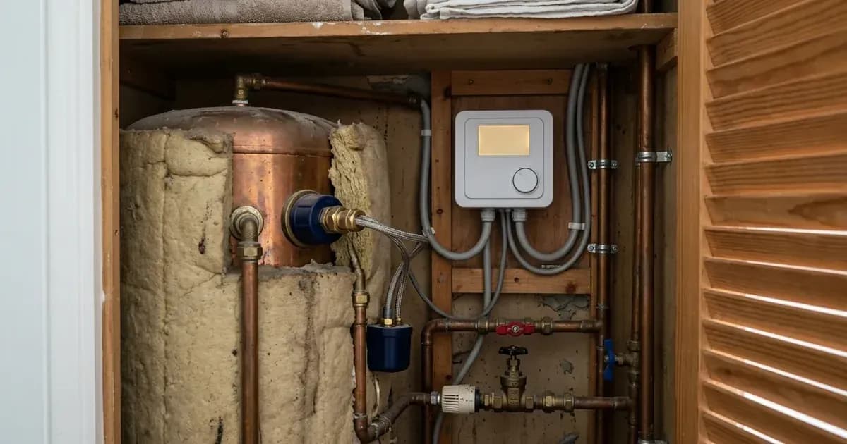
If the diverter display indicates that power is actively diverting (such as high kilowatt levels) yet the cylinder water remains stone cold, the issue is not electronic: the mechanical tank thermostat has tripped.
All modern British unvented and vented hot water cylinders incorporate a dual-function thermostat inside the immersion cap:
- Regulating Thermostat: A rotary dial allowing temperature adjustment (set to target domestic hot water temperatures).
- Thermal Safety Cutout: A manual bimetal high-limit safety button designed to prevent cylinder boiling if the regulating thermostat contacts weld shut.
Because solar diverters deliver continuous trickle power over many hours, hot water layers at the top of the cylinder can trigger this safety cutout.
Reset Procedure:
- Turn off the dedicated immersion heater switch on the wall (often marked with an indicator neon light).
- Switch off the immersion miniature circuit breaker inside your consumer unit.
- Unscrew the plastic immersion heater terminal cover on the cylinder.
- Locate the small red or black manual reset pin positioned between the electrical screw terminals.
- Firmly depress the reset button using an insulated tool until you feel an audible mechanical click.
- Refit the cover securely before restoring mains electrical power.
Frequently asked questions
Why is my solar diverter showing export on the screen but not heating my water cylinder?
If the diverter indicates active export but the immersion tank stays cold, the mechanical cylinder thermostat or internal bimetal high-limit safety thermal cutout has likely tripped and requires resetting.
Can having multiple CT clamps cause my immersion diverter to fail?
Yes. When a property has separate CT sensors for a battery inverter, an EV charger, and a solar diverter, placing the clamps too close together causes mutual magnetic induction and false readings. Manufacturers recommend a physical separation of up to 50-100cm.
What happens if the CT clamp arrow is pointing in the wrong direction?
If the CT clamp arrow is reversed, the diverter interprets domestic grid import as solar export, causing the immersion element to heat water using expensive grid electricity, or locking the device into standby when true solar export occurs.
Why does my battery charge instead of my immersion diverter heating water?
Solar diverters modulate power only when surplus energy exceeds household demand. If your hybrid battery is taking priority charging, no excess power reaches the grid boundary CT clamp until the battery reaches its target state of charge.
References
- Sunsynk Knowledge Base: Current Transformer (CT) Clamp Installation Guide — accessed 29 August 2026
- Sunsynk ECCO Hybrid Inverter User Manual — accessed 29 August 2026
Related guides
More from inverter errors & fixes.