Victron MultiPlus and Quattro Parallel Three-Phase System Configuration
Updated 16 September 2026 · By SolarNevs Research Desk, Dealer surveys + verified sources · 1 source · Method ↗
Key Takeaways
- Correct and symmetrical DC and AC wiring is critical for stable parallel three-phase Victron systems.
- All Victron VE.Bus units in a system must have the same firmware version and compatible IDs.
- Avoid over-dimensioning AC cabling, as it can lead to uneven current distribution and Power Assist issues.
- Victron products are designed for star (Y) type three-phase configurations with a distributed neutral; Delta (Δ) configurations are not supported.
- Untrained or inexperienced installers should not attempt to design or install these complex systems.
How do I configure a Victron MultiPlus or Quattro for parallel three-phase operation?
Configuring Victron MultiPlus and Quattro inverters for parallel three-phase operation requires careful attention to wiring, firmware, and settings. The most common issues arise from incorrect wiring symmetry or mismatched unit configurations. The first step is always to ensure all units are running the latest firmware and have identical compatibility IDs.
Diagnosis and Troubleshooting for Parallel Three-Phase Systems
This section outlines common symptoms and provides steps to diagnose issues in your Victron parallel three-phase system.
- Check for Phase Rotation Alarm:
- Observation: Your GX device signals a "phase rotation alarm."
- Meaning: This indicates an incorrect phase rotation between the inverter and the AC input, or a mismatch with the units' programming.
- Action: Proceed to the fix table for resolution.
- Verify Symmetrical Installation:
- Observation: Numbers and information on your GX device or VRM portal appear incorrect, or system control (e.g., input current limits) does not work properly.
- Meaning: This often points to a non-symmetrical installation, such as having a different number of units on each phase (e.g., 2 units on L1, 3 on L2, 3 on L3) when a monitoring device is connected.
- Action: Ensure your system has an equal number of units on each phase.
- Inspect AC Cabling for Current Distribution:
- Observation: You notice bad current distribution between paralleled units, or faulty Power Assist operation where the total AC input current is too low.
- Meaning: Over-dimensioning the AC cabling (using cables with too low resistance) can lead to uneven current distribution.
- Action: Review your AC cabling to ensure it is appropriately sized and symmetrical, as described in the safety section.
- Confirm Three-Phase Configuration Type:
- Observation: Certain inverter features are not operating as expected.
- Meaning: Victron products are designed for star (Y) type three-phase configurations with a distributed neutral. Delta (Δ) configurations are not supported and can cause unexpected behavior.
- Action: Verify your three-phase system is configured as a star (Y) type.
Cause and Fix Table
Symptom detail | Likely cause | Fix |
|---|---|---|
System will not accept mains input and only operates in inverter mode | Phase rotation between inverter and AC in is different to the programming of the Multis. | Swap two phases to correct wiring, or re-program the units to match the wiring rotation. If a GX device is connected, it will signal a phase rotation alarm. |
Numbers and information shown on GX device/VRM portal are wrong, controlling system (e.g., input current limits) does not work properly | Non-symmetrical installation (e.g., 2 units on L1, 3 on L2, 3 on L3) combined with any monitoring device (VE.Bus Smart Dongle, GX device). | Ensure a symmetrical installation with an equal number of units on each phase. |
Bad current distribution between paralleled units | Over-dimensioning the AC cabling (too low resistance). | Use appropriately sized AC cabling. Both DC and AC wiring needs to be symmetrical per phase: use the same length, type, and cross-section to every unit in the phase. |
Faulty Power Assist operation, total AC input current too low (undercharging battery) | Over-dimensioning the AC cabling, leading to uneven current distribution. | Use appropriately sized AC cabling. Both DC and AC wiring needs to be symmetrical per phase: use the same length, type, and cross-section to every unit in the phase. |
Certain inverter features not operating as expected | Delta (Δ) configuration used for three-phase systems. | Victron products are designed for star (Y) type three-phase configurations with a distributed neutral. Reconfigure to a star (Y) type system. |
Configuration Details for Parallel Three-Phase Systems
Proper configuration is essential for the stable operation of Victron VE.Bus products in parallel and three-phase setups.
System Sizing and Setup Tools
Victron MultiPlus and Quattro models can be combined to create powerful systems. For example, the maximum system size for 15kVA Quattros in a three-phase system is 180kVA, which consists of 12 units total, with four units on each of the three phases. When using smaller models, a maximum of five units can be paralleled on each of the three phases, totaling 15 units in a three-phase system. For instance, using 10kVA Quattros, the maximum system size is 150kVA.
To configure your system:
- Up to three units: Use the VE.Bus Quick Configure tool.
- Four units or more: Use the VE.Bus System Configurator tool.
- Individual unit settings: Activate VEConfigure from within Quick Configure or System Configurator to make settings per unit.
Firmware and Compatibility
All units in one system must be the same type and firmware version. Always update all units to the latest firmware version during commissioning of the system. Additionally, ensure that the 4-digit number in the compatibility ID of all units in the VE.Bus system is identical. For units in a single phase (parallel units), make sure they have an identical letter in the compatibility ID.
Wiring Requirements
- DC Wiring: Every DC connection on every Multi/Quattro and on every battery must be connected together to a single DC bus. Do not build systems with separated batteries on multiple (separated) DC bus structures connected to subsets of the Multi/Quattro units in the cluster, as this will not work. Ensure battery cables and jumpers between cells/batteries are properly sized.
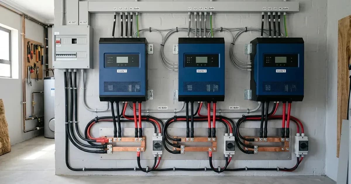
- AC Wiring: For units in parallel, both the DC and AC wiring needs to be symmetrical per phase. Use the same length, type, and cross-section to every unit in the phase. To simplify this, use a bus-bar or power-post before and after the inverter/chargers. Do not over-dimension the AC cabling, as using extra thick cabling can have negative side effects such as bad current distribution and faulty Power Assist operation.
- VE.Bus Communication: All units must be daisy chained with a VE.Bus cable (RJ-45 Cat5 or better). The sequence for this is not important. Do not use terminators in the VE.Bus network.
- Voltage Sense: Wire the voltage sense on the master of L1. All other units ignore their voltage sense input.
Settings Configuration
Settings are configured differently depending on their scope:
- Configured in the master of L1:
- All charger settings, such as absorption voltage, float voltage, and max charge current. The max charge current is multiplied by the number of units in the system.
- System frequency.
- The "Ignore AC input" function within the virtual switch configuration.
- Configured in the master of each phase:
- Inverter output voltage.
- Input current limits. The effective limit is the set limit multiplied by the number of units per phase.
- UPS function on/off.
- PowerAssist settings.
- "Accept wide input frequency range" on/off.
- "Weak AC input" on/off.
- Configured in each unit in the system:
- Country / grid code standard and other grid related values (AC high/low values).
- DC input low shut-down values.
- Self-consumption assistants, such as ESS, Hub-1 to Hub-4. These need to be loaded into each unit individually.
- PV Inverter Assistant. This needs to be loaded into each unit in the system.
- The VE.Bus BMS and the Two-Signal BMS support Assistant. These also need to be loaded in each unit in the system individually; program each Multi separately.
- Other Assistants, such as genset start/stop or relay locker, where a unique configuration can be made in each unit.
- A unique virtual switch configuration can be configured for each unit, with the exception of the "Ignore AC input" function.
System Monitoring
It is strongly recommended that a GX Family Product (e.g., Cerbo) is used in conjunction with these larger systems. Data from the VRM portal will greatly speed up support if it is required. The Victron Toolkit App can provide LED code definitions for troubleshooting.
Safety: Essential Guidelines for Complex Victron Systems
Working with parallel and three-phase inverter systems involves significant electrical hazards. Adhering to safety guidelines is paramount to prevent injury and equipment damage.
- Professional Expertise: We do not support or recommend that untrained and/or inexperienced installers work on these size systems. It is essential to consider training, equipment, and software before attempting design or installation. First, gain experience with smaller systems. It is also recommended to hire an installer that has experience with these more complex Victron systems, for both the design and the commissioning. Victron provides specific training for these systems to distributors via their regional sales manager, and advanced training theory, practical videos, and competency exams for 3 phase and parallel installation and commissioning are available on Victron Professional -> Online Training.
- DC Bus Structure: Every DC connection (on every Multi/Quattro and on every battery) has to be connected together to a single DC bus. Do not build systems with separated batteries on multiple (separated) DC bus structures connected to subsets of the Multi/Quattro units in the cluster.
- Wiring Symmetry and Sizing: For units in parallel, both the DC and AC wiring needs to be symmetrical per phase: use the same length, type, and cross-section to every unit in the phase. To make this easy, use a bus-bar or power-post before and after the inverter/chargers. Also, apply the same torque on all connections. Beware of sizing the battery cable and jumpers between cells/batteries.
- Fusing: Each unit needs to be fused individually for AC. Make sure to use the same type of fuse on each unit due to same resistance. Consider using mechanically connected fuses, so that if one trips, they all trip, leading to a clear fault. For both AC and DC fusing and protection, consult the product manual for details and recommended ratings.
- AC Cabling: Do not over-dimension the AC cabling. Using extra thick cabling has negative side effects, such as bad current distribution and faulty Power Assist operation.
- Three-Phase Configuration: Our products have been designed for a star (Y) type three-phase configuration. In a star configuration, all neutrals are connected, a so-called "distributed neutral." We do not support a delta (Δ) configuration.
- VE.Bus Network: All units must be daisy chained with the VE.Bus cable (RJ-45 Cat5 or better). Do not use terminators in the VE.Bus network.
- AES Functionality: Note that AES (Automatic Economy Switch) is only operational in stand-alone systems, not in parallel and multi-phase systems.
When to call a technician instead
Given the complexity and safety requirements, it is strongly advised to call a qualified and experienced Victron technician if you are not fully confident in your ability to design, install, or troubleshoot these systems. Untrained and/or inexperienced installers should not work on these size systems. Incorrect installation can lead to system instability, equipment damage, or electrical hazards. The Victron manual explicitly states that professional training and experience are essential before attempting design or installation.
Frequently asked questions
What is the maximum system size for Victron 15kVA Quattros in a three-phase setup?
The maximum system size for 15kVA Quattros in a three-phase system is 180kVA. This configuration consists of 12 units in total, with four units on each of the three phases.
What is the maximum number of units that can be paralleled on a single phase with smaller Victron models?
When using smaller models, a maximum of five units can be paralleled on each of the three phases, totaling 15 units in a three-phase system. For example, with 10kVA Quattros, the maximum system size is 150kVA.
What is the importance of symmetrical wiring in a Victron parallel system?
Both DC and AC wiring must be symmetrical per phase, meaning the same length, type, and cross-section to every unit. This ensures even current distribution and prevents issues like faulty Power Assist operation.
How do I correct a phase rotation alarm in a Victron three-phase system?
If a GX device signals a phase rotation alarm, you need to swap two phases to correct the wiring rotation or re-program the units to match the existing wiring rotation.
Which Victron configuration tool should I use for a system with four or more units?
For systems with four units or more, you should use the VE.Bus System Configurator. For systems with up to three units, VE.Bus Quick Configure can be used.
References
- VE.Bus Parallel and Three-Phase Systems Manual — accessed 23 August 2026
Related guides
More from sizing, net billing & installation.