Growatt SPF ES Inverter WiFi Setup for Remote Monitoring
Updated 6 September 2026 · By SolarNevs Research Desk, Dealer surveys + verified sources · 1 source · Method ↗
Key Takeaways
- The WiFi / GPRS module is an optional, plug-and-play device for remote monitoring.
- Monitoring software is available for download from the official Growatt website,
www.ginverter.com. - All wiring must be performed by a qualified person.
- If you encounter persistent issues after following basic setup steps, contact a professional technician.
How to Set Up Your Growatt SPF ES Inverter for WiFi Monitoring
Setting up WiFi monitoring for your Growatt SPF ES series inverter allows you to track your solar system's performance from anywhere using a mobile phone or website. This process involves installing an optional WiFi / GPRS module and then configuring the monitoring software. The Growatt SPF 3500 ES and SPF 5000 ES models support this functionality.
The most common reason for issues during setup is an incorrectly installed WiFi / GPRS module or a failure to download and configure the correct monitoring software. Ensure the module is securely connected to the designated port and that you are using the software from the official source.
Diagnosis and Setup Steps
Follow these steps to set up WiFi monitoring for your Growatt SPF ES inverter. Remember that all wiring must be performed by a qualified person.
- Obtain the WiFi / GPRS Module: The WiFi / GPRS module is a plug-and-play monitoring device, but it is optional and typically purchased separately. Ensure you have the correct module compatible with your Growatt SPF ES inverter.
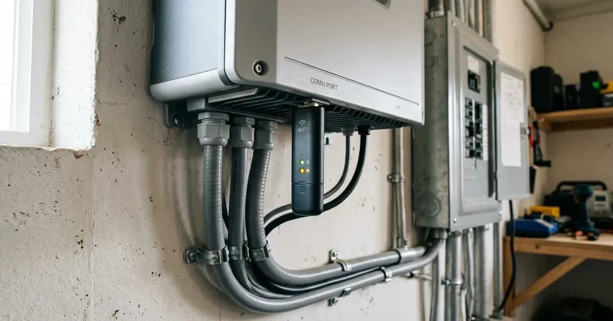
- Locate the WiFi/GPRS Communication Port: On your Growatt SPF ES inverter, identify the dedicated WiFi/GPRS communication port. This port is specifically designed for the monitoring module.
- Install the WiFi Module: Before proceeding, ensure the inverter is completely powered down and isolated from all power sources (AC, DC, and battery), and allow sufficient time for internal capacitors to discharge. Improper handling may void your warranty. Carefully plug the WiFi / GPRS module into the WiFi/GPRS communication port on your inverter. Ensure it is seated firmly and correctly.
- Download Monitoring Software: The monitoring software is downloadable from the official Growatt website,
www.ginverter.com. Visit this website using a computer or mobile device to download the appropriate application or software for your system. - Install and Configure Software: Install the downloaded software on your mobile phone or computer. Follow the instructions provided with the WiFi / GPRS module or within the software itself to configure the connection to your inverter. This typically involves connecting to the module's temporary WiFi network, entering your home WiFi credentials, and then registering your inverter.
- Verify Connection: Once configured, the software should display data from your PV system. Check the application or website interface to confirm that the inverter is communicating and reporting data correctly. You should be able to monitor the status of your PV system from your mobile phone or from the website anytime anywhere.
Common Setup Issues and Solutions
Symptom detail | Likely cause | Fix |
|---|---|---|
WiFi module not recognized by inverter | Module not properly seated or incompatible | Ensure the WiFi / GPRS module is firmly plugged into the WiFi/GPRS communication port. Verify the module is designed for the Growatt SPF ES series. |
Monitoring app shows "offline" or no data | Incorrect network configuration or no internet access | Double-check your WiFi network credentials entered during setup. Ensure your home network has an active internet connection. |
Unable to download software | Incorrect website or internet connectivity issue | Access |
Inverter displays communication error (e.g., related to external devices) | Conflict with other communication devices or settings | If you have other communication devices connected, ensure they are not interfering. Consult the inverter manual for specific communication settings, such as those for BMS communication (Program 36), if applicable. For issues like a "BMS communication error" (Code 20), check the communication line and BMS protocol type setting. |
Monitoring and Communication Features
The Growatt SPF ES series inverters, including the SPF 3500 ES and SPF 5000 ES, are designed with various communication ports to facilitate monitoring and system expansion.
- WiFi/GPRS Communication Port: This is where the optional WiFi / GPRS module connects, enabling remote monitoring of your PV system's status.
- USB Communication Port: This port is available for local data access or specific configurations.
- BMS Communication Port: This port supports CAN/RS485 protocols for communication with compatible lithium batteries that have a Battery Management System (BMS). When using a lithium battery with BMS communication, you can select "LI" in Program 05: Battery type. For lithium batteries without BMS communication, "User-Defined 2" can be selected, which, like "User-Defined", allows you to set battery charge voltage and low DC cut-off voltage in programs 19, 20, and 21.
- RS485 Communication Port (for expansion): An additional RS485 port is available for other expansion purposes, such as connecting to external devices or for parallel communication. For parallel systems, ensure parallel communication cables are connected well to avoid "CAN fault" (Code 80).
The ability to monitor your system remotely is a key benefit of the Growatt SPF ES inverters. It allows you to track energy production, consumption, and battery status, helping you optimize your solar power usage. For more details on understanding inverter messages, refer to our guide on Growatt SPF ES Inverter Fault Codes. If you are configuring battery settings, our article on Growatt SPF ES Battery Pairing Settings provides further guidance.
Safety
Working with solar inverters and battery systems involves electrical hazards. Always prioritize safety.
- Qualified Personnel: All wiring must be performed by a qualified person. Do not attempt electrical work if you are not certified or experienced.
- Disconnection: To reduce the risk of electric shock, disconnect all wirings before attempting any maintenance or cleaning. Turning off the unit alone will not eliminate this risk.
- No Disassembly: Do not disassemble the unit. If service or repair is required, take it to a qualified service center. Incorrect re-assembly can lead to electric shock or fire.
- Grounding: The inverter must be connected to a permanent grounded wiring system. Ensure compliance with local requirements and regulations for installation.
- Breakers: Install a separate AC breaker between the inverter and the AC input power source. For the SPF 3500 ES, a 40A AC breaker is recommended, and for the SPF 5000 ES, a 50A AC breaker is recommended. Also, install a separate DC circuit breaker between the inverter and PV modules.
When to call a technician instead
While installing the WiFi / GPRS module is designed to be plug-and-play, the overall inverter system involves complex electrical connections. You should call a qualified technician if:
- You are unsure about any wiring or electrical connections. All wiring must be performed by a qualified person.
- The inverter displays fault codes that you cannot resolve using the manual's troubleshooting steps, especially internal component failures (e.g., Fault code 09/53/57).
- The system fails to power on or operate correctly after installing the WiFi / GPRS module and you have verified basic connections.
- You encounter persistent communication errors with the WiFi / GPRS module or monitoring software despite following all setup instructions, including issues like "Li battery can't communicate to the inverter" (Code 20), "CAN fault" (Code 80), "Internal communication error" (Code 62), "Host loss" (Code 81), "BMS communication loss" (Code 33), "The input status is different in parallel system" (Code 15), "Input phase is not correct" (Code 16), "The output phase not correct in parallel" (Code 17), or "Negative power fault" (Code 60).
- You need to open the inverter's enclosure for any reason. Do not disassemble the unit yourself; take it to a qualified service center.
Attempting repairs or modifications without proper qualifications can void your warranty and pose significant safety risks.
Still showing the fault? Book a technician
If the steps above did not clear it, tell us the inverter or battery and the exact code. We pass it to a technician who covers your city; visit charges are quoted before they come.
How this pays for the site: the technician or verifier pays SolarNevs a fixed introduction fee. Nobody pays to be recommended, and you are free to use our free guides instead.
Frequently asked questions
What is the Growatt WiFi module for?
The WiFi / GPRS module for Growatt SPF ES inverters allows you to monitor your PV system's status remotely. You can access this information from a mobile phone or through a website anytime anywhere.
Where can I download the Growatt monitoring software?
The monitoring software for your Growatt SPF ES inverter is available for download from the official Growatt website, www.ginverter.com.
Is the WiFi module included with the Growatt SPF ES inverter?
No, the WiFi / GPRS module is an optional, plug-and-play monitoring device. It is not included as standard with the SPF 3500 ES or SPF 5000 ES inverters.
Which Growatt inverters support this WiFi setup?
This WiFi setup is applicable to the Growatt SPF 3500 ES and SPF 5000 ES off-grid solar inverters, which are part of the SPF ES series.
Can I install the Growatt WiFi module myself?
Yes, the WiFi / GPRS module is designed as a plug-and-play device. However, for safety, always ensure the inverter is completely powered down and isolated from all power sources (AC, DC, and battery) and allow sufficient time for internal capacitors to discharge before plugging in or unplugging the module. Improper handling may void your warranty. All other electrical wiring and connections to the inverter system must be performed by a qualified person.
References
- Growatt Off Grid Solar Inverter SPF 3500 ES SPF 5000 ES Manual — accessed 23 August 2026
Related guides
More from inverter errors & fixes.