Fronius Smart Meter TS Wiring and Dynamic Limitation Guide
Updated 15 September 2026 · By SolarNevs Research Desk, Dealer surveys + verified sources · 2 sources · Method ↗
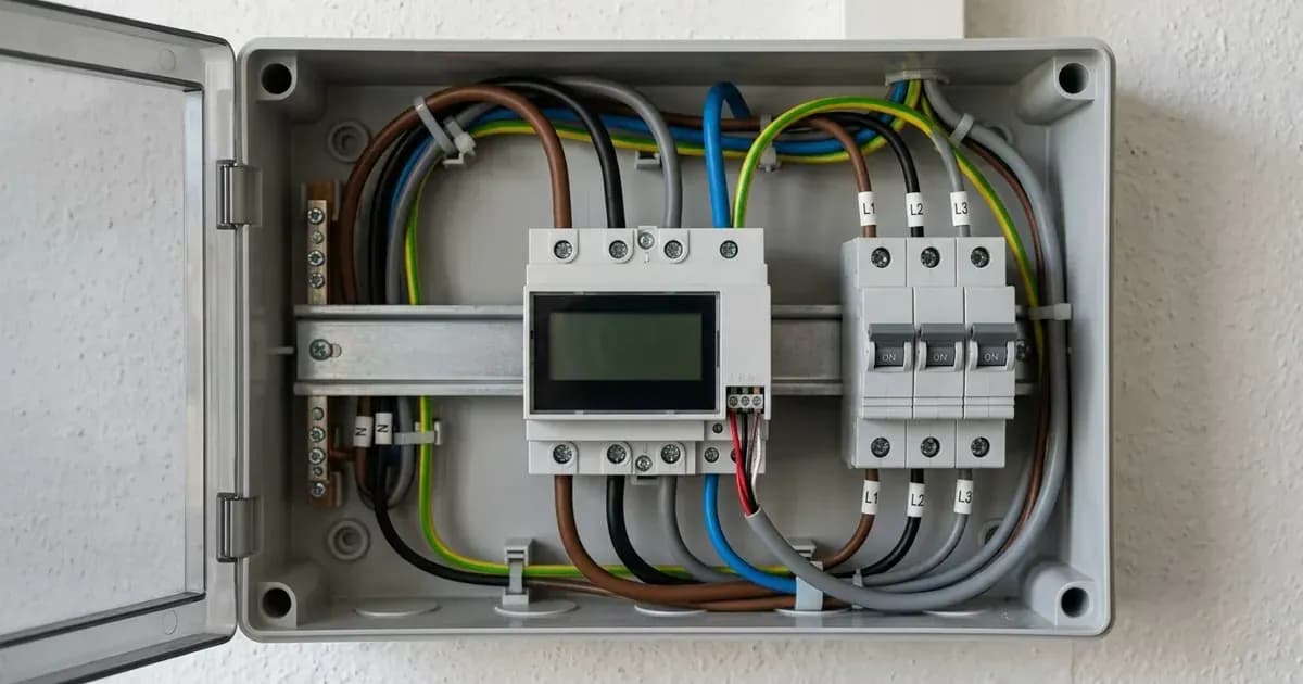
The Fronius Smart Meter TS is a crucial component for monitoring energy flow and managing grid export in a Fronius solar PV system. This guide details the correct wiring procedures for the Fronius Smart Meter TS 65A-3, 100A-1, and 5kA-3 models, along with configuring dynamic export limitation.
Why Install a Fronius Smart Meter TS?
System Component / Step | Technical Requirement & Wiring Rule | Operational Function & Verification |
|---|---|---|
Grid Incomer Placement | Install at main incoming supply point before sub-distribution | Records all bidirectional energy flows between premises and grid |
Modbus RS485 Wiring | Shielded twisted-pair CAT5e or CAT6 communication cable | Eliminates EMI and connects meter to GEN24 Plus / SnapINverter |
Bus Termination | Activate terminating resistor switch on final bus device | Eliminates signal reflections for reliable Modbus RTU telemetry |
Phase Rotation (3-Phase) | Verify L1, L2, L3 phase sequence before applying load | Prevents measurement errors on direct-connect and CT-connected meters |
Dynamic Export Control | Configure zero feed-in or custom caps in Solar.start interface | Dynamically modulates inverter output to comply with grid rules |
Safety & Isolation | De-energize board; wait 5 minutes for capacitor discharge | Prevents electrical shock and ensures protective earthing integrity |
The Smart Meter TS provides bidirectional energy flow measurement, which is essential for accurate self-consumption calculations and dynamic export control. It enables your Fronius inverter to enforce zero grid feed-in or custom export limits, complying with local grid regulations. Accurate meter connection also allows Fronius Solar.web to display live generation, self-consumption, and grid power flow.
Models Covered
This guide applies to the Fronius Smart Meter TS models:
- Fronius Smart Meter TS 65A-3
- Fronius Smart Meter TS 100A-1
- Fronius Smart Meter TS 5kA-3
Smart Meter TS Installation Location
The Fronius Smart Meter TS must be installed at the main grid incoming supply point. This placement is critical to record all bidirectional energy flows between your premises and the electrical grid.
Modbus RTU RS485 Communication Wiring
The Fronius Smart Meter TS communicates with compatible inverters via a Modbus RTU RS485 interface.
Cable Requirements
Use shielded twisted-pair CAT5e or CAT6 communication cable. This type of cable helps prevent electromagnetic signal interference, ensuring reliable data transmission.
Terminal Connections
Fronius GEN24 Plus inverters communicate with Smart Meter TS devices via shielded Modbus RTU RS485 wiring. Connect the Modbus RS485 communication lines between the Smart Meter TS and the inverter.
Terminating Resistor
Activate the terminating resistor switch on the final device of the Modbus RS485 communication line. This prevents signal reflections and ensures stable communication across the bus.
Three-Phase Meter Specifics
For three-phase direct-connect meters, ensure the phase rotation sequence (L1, L2, L3) is correct before applying load. Incorrect phase rotation can lead to inaccurate readings or system malfunctions.
Configuring Dynamic Export Limitation
Dynamic feed-in limitation allows you to control the amount of PV power exported to the grid, including enforcing zero grid feed-in.
Solar.start Configuration
To set up dynamic export limitation, use the Solar.start web interface. Here, you can configure dynamic export limitation to enforce zero grid feed-in or custom limits according to your requirements or grid operator demands.
Monitoring with Solar.web
Once correctly installed and configured, the accurate meter connection enables Fronius Solar.web to display live generation, self-consumption, and grid power flow. This provides comprehensive insights into your system's performance.
Safety First
Working with electrical systems carries inherent risks. Always prioritize safety.
- Isolation: De-energize the main electrical distribution board before connecting voltage measurement lines and meter terminals.
- Capacitor Discharge: Switch off all AC and DC isolators and wait at least 5 minutes before servicing electrical connections. This allows internal capacitors to discharge, preventing shock hazards.
- Earthing: Ensure the inverter chassis and meter enclosures are securely bonded to earth. This provides protective earthing, a critical safety measure.
- Certified Anti-Islanding: The system complies with international grid connection and microgeneration safety standards, including certified anti-islanding protection.
Compatible Inverters
The Fronius Smart Meter TS works universally with Fronius Primo GEN24, Symo GEN24, and SnapINverter product families.
Get three dated installer quotes for this system
Tell us your city and your summer electricity bill. We pass your number to up to three vetted installers who quote against the surveyed prices on this page, so nobody can quote you Rs 5 a watt over market.
How this pays for the site: installers pay SolarNevs a fixed introduction fee when we pass them a genuine enquiry. They cannot pay to appear higher, and our surveyed prices are published before any introduction. You can also take our dated price tables straight to any installer.
Frequently asked questions
What are the essential requirements for fronius smart meter ts wiring and dynamic limitation guide?
Verify system specifications, local regulations, and standard installation safety procedures prior to commissioning.
How do I ensure regulatory compliance?
Ensure all equipment is approved on relevant regulatory registries and installed by accredited certified professionals.
References
- Fronius Smart Meter TS 65A-3 Operating Instructions — accessed 27 August 2026
- Fronius Quick Guide: Setting up Export Limiting using the Fronius Smart Meter — accessed 27 August 2026
Related guides
More from sizing, net billing & installation.