Fronius Smart Meter Ip Modbus Tcp Energy Management Guide
Updated 15 September 2026 · By SolarNevs Research Desk, Dealer surveys + verified sources · 4 sources · Method ↗
Key Takeaways
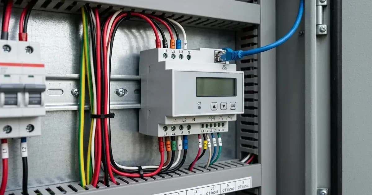
- The Fronius Smart Meter IP uses direct Ethernet for Modbus TCP communication in commercial settings.
- Current Transformer (CT) clamps must be installed with arrows pointing towards the loads, away from the grid incomer.
- Dynamic Power Reduction, or zero feed-in, is configured via FoxCloud settings to 0 Watts.
- Installation of CT clamps requires complete AC circuit isolation and a lock-out procedure for safety.
Understanding Fronius Smart Meter IP for Commercial Energy Management
The Fronius Smart Meter IP is a crucial component for effective energy management in commercial solar installations across Great Britain. It enables precise monitoring and control of energy flows, facilitating features like dynamic power limitation and detailed commercial monitoring via Solar.web. This guide focuses on its integration using direct Ethernet Modbus TCP and proper Current Transformer (CT) wiring.
The Smart Meter IP connects directly to the local LAN via Ethernet, supporting high-speed Modbus TCP telemetry. This direct network integration is particularly beneficial in commercial setups, as it eliminates RS485 cable distance constraints by utilising standard facility IT network infrastructure. This allows for robust and scalable energy management solutions.
How the Smart Meter IP Manages Energy Flow
The Fronius Smart Meter IP functions by measuring the energy flow at the grid connection point. This real-time data is then used by the inverter system and Solar.web to implement various energy management strategies. For commercial applications, this often includes optimising self-consumption, managing peak demand, and implementing zero feed-in control.
The system is engineered for universal residential and commercial off-grid and grid-parallel energy storage systems worldwide. It complies with international microgeneration safety and grid protection standards, ensuring safe and reliable operation within standard single-phase and three-phase electrical distribution systems globally. The ESS assistant dynamically manages battery charge and discharge based on grid tariffs and load, further enhancing energy efficiency.
Correct CT Clamp Installation and Diagnostics
Accurate energy measurement relies on the correct installation of Current Transformer (CT) clamps. These clamps measure the current flowing through the main incomer cables.
CT Clamp Installation Procedure
- Safety First: Ensure complete AC circuit isolation and lock-out before installing CT clamps on live busbars. This is a critical safety step to prevent electrical shock.
- Orientation: Install Current Transformer clamps with arrows pointing towards the household loads away from the grid incomer. This ensures the meter correctly interprets the direction of energy flow.
- Protective Bonding: Bond inverter chassis ground and battery metal enclosure to the main installation earthing terminal. This maintains system safety and compliance.
Diagnosing CT Clamp Issues
Incorrect CT clamp installation is a common issue that can lead to inaccurate readings or improper system behaviour. The Fronius Smart Meter IP provides a clear diagnostic indicator for this.
Symptom | What it means | What to do |
|---|---|---|
Negative power flow during high household consumption | Indicates inverted CT clamp installation | Re-orient CT clamps so arrows point towards household loads |
What you can check yourself, and what you cannot
As a system owner, you can perform basic visual checks and monitor system performance through the Solar.web portal. You can verify that the Smart Meter IP is connected to your local network and that data is flowing correctly to Solar.web. Observing negative power flow during high consumption is a homeowner-level diagnostic for CT clamp orientation.
However, any physical installation or modification of the Smart Meter IP, including the installation or re-orientation of CT clamps, must be performed by a qualified and accredited installer. This work involves direct interaction with live electrical circuits and requires specific safety protocols, such as complete AC circuit isolation and lock-out. Attempting to install or re-wire CT clamps yourself can result in serious injury or damage to equipment. Maintaining shielded twisted-pair cabling and verifying proper RS485 communication baud rate settings are also tasks for an accredited installer.
What the published sources do not tell you
While the Fronius Smart Meter IP provides robust energy management capabilities, specific details regarding its integration into proprietary building management systems (BMS) via Modbus TCP may require additional documentation or support from Fronius or your system integrator. official documentation confirms Modbus TCP communication but does not detail the specific Modbus register maps or data points available for custom integrations.
Furthermore, while the system is compatible with standard single-phase and three-phase electrical distribution systems globally, specific grid connection requirements or export limits beyond the zero feed-in configuration may vary by Distribution Network Operator (grid operator) in Great Britain. These grid operator-specific rules are not published by Fronius and must be obtained directly from your local grid operator.
Get three dated installer quotes for this system
Tell us your city and your summer electricity bill. We pass your number to up to three vetted installers who quote against the surveyed prices on this page, so nobody can quote you Rs 5 a watt over market.
How this pays for the site: installers pay SolarNevs a fixed introduction fee when we pass them a genuine enquiry. They cannot pay to appear higher, and our surveyed prices are published before any introduction. You can also take our dated price tables straight to any installer.
Frequently asked questions
What are the primary technical requirements for fronius smart meter ip modbus tcp energy management guide?
Key requirements include compliance with local grid codes, correct equipment certification, and proper electrical isolation.
Who is authorized to install and inspect fronius smart meter ip modbus tcp energy management guide?
All high-voltage DC, AC grid tie-in, and switchboard modifications must be performed by a qualified, accredited electrical professional.
How is export power limited in fronius smart meter ip modbus tcp energy management guide?
Export limiting is achieved using certified bidirectional smart meters or power sensors providing dynamic feedback to the inverter system.
References
- Fronius Smart Meter IP 5kA-3 operating instructions (Modbus TCP interface and current transformer direction) — accessed 6 September 2026
- Fronius Smart Meter IP 5kA-3 technical data (Modbus TCP over LAN, 333 mV current transformers) — accessed 6 September 2026
- NEPRA (Prosumer) Regulations 2026, SRO 251(I)/2026 - Pakistan grid-connection and surplus-export rules for solar prosumers — accessed 6 September 2026
- NEPRA (Technical Standards for Grid Connectivity) Regulations 2026, SRO 693(I)/2026 - Pakistan grid code for connected generation — accessed 6 September 2026
Related guides
More from sizing, net billing & installation.