Sunsynk High Voltage Battery Series Stacking and BMU Wiring Guide
Updated 8 September 2026 · By SolarNevs Research Desk, Dealer surveys + verified sources · 16 sources · Method ↗
Key Takeaways
- Sunsynk High Voltage (HV) battery systems require a minimum of four modules to power the Battery Management Unit (BMU).
- Correct wiring and inverter settings for "Parallel bat1&bat2" are critical for proper communication and discharge rates.
- Unbalanced battery modules can cause sudden State of Charge (SOC) changes and require specific rebalancing procedures.
- High voltage installations, including wiring and fuse selection, must be performed by a qualified, registered person due to significant safety risks.
Understanding Sunsynk High Voltage Battery Systems
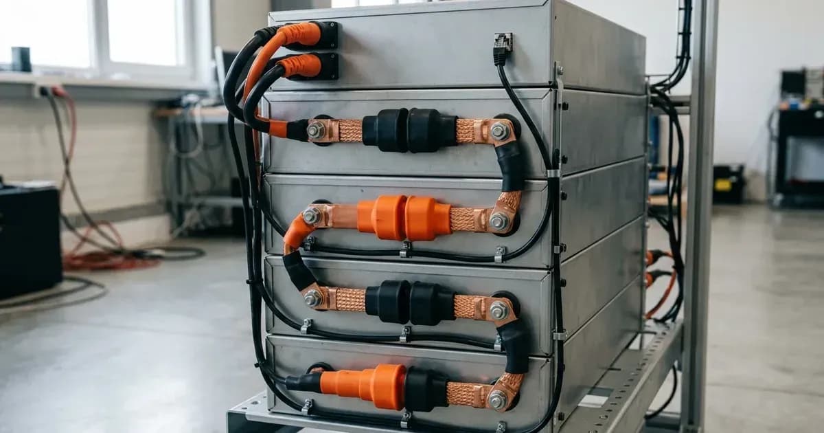
Sunsynk High Voltage (HV) battery systems are designed for larger solar installations, often paired with inverters such as the 50kW model. These systems are modular, meaning they consist of multiple individual battery modules stacked together. A Battery Management Unit (BMU) oversees the operation of these modules, ensuring they work together efficiently and safely.
For the BMU to function correctly and power the system, a minimum of four HV battery modules must be connected. This applies whether you are setting up a new system or expanding an existing HV battery rack.
Connecting Your Sunsynk HV Battery Modules
Connecting Sunsynk HV battery modules involves careful attention to both power cabling and Battery Management System (BMS) communication. The method you choose depends on the number of battery racks and how you want them to operate.
HV Battery Connection Methods
Sunsynk outlines two primary methods for connecting HV battery racks:
- Independent Racks with Independent BMS Communications:
- This configuration is recommended for systems with one or two battery racks.
- Each battery stack operates independently, sending its own individual BMU data to the inverter.
- Crucially, the "Parallel bat1&bat2" setting in the inverter must be disabled.
- Paralleling Battery Inputs and Linking BMS Communications:
- This configuration is suitable for one or more battery connections where a combined BMU data stream is desired.
- The BMS is shared between battery stacks, providing a single data set to the inverter.
- For this setup, the "Parallel bat1&bat2" setting in the inverter MUST BE ENABLED.
Incorrect connection or inverter settings can lead to issues such as voltage discrepancies between the BMU display and the inverter, or the inverter failing to power on from the battery.
Powering On the Inverter from HV Battery Only
If you need to power on your inverter using only the HV battery, follow these steps carefully:
- Ensure the positive and negative power cables from the BMU are connected to the inverter's battery terminals.
- Connect the BMS Communication cable from the PCOM port (located at the back of the BMU) to the BMS 1 input inside the inverter.
- Switch on the circuit breaker for the battery system and press the start button on the BMU.
- Check the BMU number displayed on its LCD screen; this number should match the total count of connected batteries. The BMU password to access certain data is 123.
- Once verified, turn the BMU off using its start button and then switch off the circuit breaker.
- Wait for 2 minutes.
- Restart the BMU by switching on the circuit breaker and then pressing the start button.
- Finally, press the ON/OFF button on the side of the inverter.
HV Battery System Settings Summary
The following table summarises key settings and parameters for Sunsynk HV battery systems:
Setting/Parameter | What it does | What to set it to / Condition |
|---|---|---|
Minimum HV Battery Modules | Required to power the BMU | 4 |
HV Battery Connection Method 1 | Independent racks, independent BMS communication | "Parallel bat1&bat2 must be disabled in the settings." |
HV Battery Connection Method 2 | Paralleling battery inputs, linking BMS communications | "Parallel bat1&bat2 MUST BE ENABLED in the settings." |
HV Battery Discharge (Bat1 only) | Maximum discharge current from a single battery port | 50 Amps |
HV Battery Discharge (Both ports, 1 BMS) | Maximum discharge current when "Parallel Bat1&2" is enabled | 100 Amps |
HV Battery Discharge (Each port, own battery) | Maximum discharge current when each input is independently connected | 100 Amps |
BMU Password | Accessing certain data on the HV series battery BMU | 123 |
Adding New HV Battery Modules | Minimum number of batteries for expansion | Four |
BMU Number Adjustment | Ensures correct communications when adding modules | Accessed on BMU display by pressing person icon, entering password 123. |
HV Battery Calibration | Recommended charging frequency to 100% SOC | Every 7 to 10 days |
HV Batteries Force Charge (50kW Inverter) | Initial charge on start-up | From Grid to 100% SOC for BMU calibration. May take up to 24 hours. |
Maintaining Balance and Performance
Maintaining balanced State of Charge (SOC) across all battery modules is crucial for the longevity and performance of your Sunsynk HV battery system. Unbalanced batteries can lead to issues like unexpected grid force charges or sudden drops in reported SOC.
Addressing Unbalanced Batteries
Batteries can become unbalanced if there is a voltage difference between modules, if they don't regularly reach 100% SOC for BMS recalibration, or if a new battery is added without matching its SOC and voltage.
If your HV battery SOC suddenly increases or decreases, it likely means one or more modules have a much lower SOC than the rest. To rectify this:
- Disconnect each battery module.
- Adjust the "Number of Batteries" setting in the BMU to match only the number of batteries you are about to charge (minimum 4).
- Reconnect only the low SOC battery modules and charge them until their SOC matches the rest of the modules.
- Reconnect all battery modules in the HV rack.
- Reset the "Number of Batteries" in the BMU back to the total count of modules.
- Perform a grid charge of all HV batteries to 100% to allow the BMS to recalibrate.
For general battery unbalance, especially in systems with two or more batteries, using a DC busbar is recommended to help maintain voltage balance. If a busbar is not feasible, double up the positive and negative connections at either end of the stack.
Battery Calibration
The BMU recalibrates the combined SOC percentage when the batteries reach 100% SOC. To ensure accurate readings and optimal performance, ensure your batteries are charged to 100% approximately every 7 to 10 days. For 50kW inverters, the initial switch-on will trigger a force charge from the grid to 100% for BMU calibration, which can take up to 24 hours.
Critical Safety Considerations for HV Battery Systems
Working with high voltage battery systems carries significant risks. Always prioritise safety and ensure all work is carried out by qualified professionals.
DC Isolator and Fuse Ratings
For a 50kW inverter with a series battery connection, the recommended fuse rating is 120A. This is a critical safety component to protect against overcurrents.
Battery Cable Sizing
The battery cables supplied with Sunsynk batteries are typically 25mm² copper cables. These cables should NEVER exceed 122.5A. Exceeding this current can damage both the inverter and the batteries, and will void your manufacturer warranty.
Pre-charge for HV Battery Recharging
If an HV battery needs recharging from a completely discharged state, a specific pre-charge procedure is required. This must be done with a DC charger capable of producing a voltage of up to 52V. The charger should be set to output 52V at 1A. The low amperage is crucial to prevent cell damage.
Safety Warning: Using a DC charger for pre-charging can be dangerous if the amperage is too high or if the process is not monitored. Over-voltage can damage lithium cells and cause fires. These batteries must NOT be left unattended overnight whilst charging. Eye protection is essential when working with batteries.
Voltage Difference Safety Mechanism
As a safety mechanism, if there is a difference of 1.5V or larger between the inverter's V-Batt reading and the BMS Voltage, the inverter will stop the flow of current between itself and the battery. This protects against potential system shorts or loose connections.
Cold Temperature Operation
Sunsynk HV batteries are designed to protect themselves in cold conditions. If the cell temperature within the battery drops to 0°C, the battery's charge rate will gradually diminish to zero. This prevents charging from the grid or solar photovoltaic sources. Even in temperatures of 0°C or below, the battery retains the capability to discharge to the load. To restore normal charging, the cell temperature must rise above 12°C.
What You Can Adjust and When to Call a Professional
As a system owner, you can monitor your HV battery system's performance, check for fault codes on the BMU display, and ensure the battery calibration schedule is met. You can also adjust the "Number of Batteries" setting on the BMU if you are expanding your system, using the password 123.
However, any work involving the physical wiring of HV battery modules, selecting fuse ratings, or making changes to inverter settings that affect grid protection or export (such as "Parallel bat1&bat2") must be performed by a qualified and registered person. In South Africa, this work requires a Certificate of Compliance (CoC). Attempting to modify high voltage wiring or grid-related settings without proper qualifications can be extremely dangerous, void warranties, and breach your connection agreement with Eskom or your municipality.
What the Published Sources Do Not Tell You
While Sunsynk provides valuable guidance on HV battery connection methods and operational procedures, there are some areas where more specific detail is not readily available in the provided documentation:
- Specific HV Battery Models and Detailed Specifications: The documents refer generally to "HV Batteries" or "HV battery racks" without providing specific model numbers, capacities, voltage ranges, or maximum charge/discharge currents per module in a structured format. This means specific performance figures for individual modules are not detailed.
- Detailed BDU Wiring Diagrams: The term "BMU" (Battery Management Unit) is consistently used for control, and while connection methods are described, explicit wiring diagrams for a "Battery Distribution Unit" (BDU) as a distinct component are not provided. The information focuses on BMU connections.
- Pre-charge Resistor Circuit: The pre-charge process is described using a DC charger for individual modules, but there is no explicit mention or description of a "pre-charge resistor circuit" as a distinct component or method for initial system power-up.
- Comprehensive HV Battery Fault Codes: Only one general battery fault code (F51 for cold temperature) is mentioned. While there's a general instruction to "check fault codes on the BMU," a specific list of fault codes for HV batteries is not detailed.
- Internal Series Cell Balancing Mechanisms: The documentation focuses on balancing the overall battery stack (e.g., by charging to 100% or re-charging low modules). It does not detail the internal series cell balancing mechanisms or specifications within individual HV battery modules.
Frequently asked questions
What is the minimum number of Sunsynk HV battery modules required?
Sunsynk High Voltage battery systems require a minimum of four battery modules to power the Battery Management Unit (BMU). This minimum applies when setting up a new system or expanding an existing one.
How do I connect multiple Sunsynk HV battery racks?
You can connect multiple HV battery racks either independently, each with its own BMS communication, or by paralleling the battery inputs and linking BMS communications between racks. The choice depends on the number of racks and requires specific inverter settings for 'Parallel bat1&bat2'.
What is the password for the Sunsynk HV battery BMU?
The password required to access certain data on the Sunsynk HV series battery BMU is 123. This is used for adjustments like setting the number of batteries.
Why is my Sunsynk HV battery State of Charge (SOC) suddenly changing?
A sudden increase or decrease in HV battery SOC often indicates that one or more battery modules within the rack have a significantly lower SOC than the others. This requires a specific rebalancing procedure involving individual module charging and recalibration.
How often should Sunsynk HV batteries be charged to 100% for calibration?
To ensure proper calibration of the Battery Management Unit (BMU) and accurate State of Charge (SOC) readings, Sunsynk HV batteries should be charged to 100% approximately every 7 to 10 days.
References
- Sunsynk Support: HV Batteries - Adding a New Battery Module — accessed 27 August 2026
- Sunsynk Support: High Voltage Battery Settings — accessed 27 August 2026
- Sunsynk Support: HV Batteries - Requesting a Force Charge — accessed 27 August 2026
- Sunsynk Support: Unbalanced Batteries — accessed 27 August 2026
- Sunsynk Support: Adding a New Battery to an Existing Pack — accessed 27 August 2026
- Sunsynk Support: HV Battery SOC Suddenly Increases or Decreases — accessed 27 August 2026
- Sunsynk Support: HV BMU Screen Shows Different Voltage — accessed 27 August 2026
- Sunsynk Support: High Voltage Powering on an Inverter from Battery Only — accessed 27 August 2026
- Sunsynk Support: HV Battery Connection Methods — accessed 27 August 2026
- Sunsynk Support: HV Battery BMU Password — accessed 27 August 2026
- Sunsynk Support: Recommended Fuse Ratings — accessed 27 August 2026
- Sunsynk Support: High Voltage Battery Recharging — accessed 27 August 2026
- Sunsynk Support: Battery Cable Sizing — accessed 27 August 2026
- Sunsynk Support: V-Batt vs. BMS Voltage — accessed 27 August 2026
- Sunsynk Support: Winter Charging — accessed 27 August 2026
- Sunsynk Support: Viewing Sunsynk Battery Data on Mobile App — accessed 27 August 2026
Related guides
More from inverter errors & fixes.