Sunsynk BMS CAN Bus and Multi-Tower High Voltage Battery Sync Guide
Updated 16 September 2026 · By SolarNevs Research Desk, Dealer surveys + verified sources · 14 sources · Method ↗
Key Takeaways
- Multi-tower high-voltage (HV) battery synchronization relies on accurate Battery Management System (BMS) communication and correct addressing.
- RJ45 cables are used for CANbus daisy chaining between batteries and to the inverter, with CAN-H on pin 4 and CAN-L on pin 5.
- DIP switches on each battery module configure master and slave roles, which is critical for proper system operation.
- Battery unbalance can occur if interconnecting cables are not of equal length or if batteries do not regularly reach 100% State of Charge (SOC).
- Physical wiring and initial DIP switch configuration are tasks for a registered person, as incorrect setup can lead to system faults or damage.
How Sunsynk Inverters Manage Multiple High-Voltage Battery Towers
Sunsynk inverters are designed to manage multiple battery units, including high-voltage (HV) battery towers, to meet the energy demands of larger installations. This capability is crucial for systems requiring significant energy storage, often seen in South African homes and businesses managing load-shedding. The effective operation of such a system depends on seamless communication between the inverter and each battery module, primarily facilitated by the Battery Management System (BMS) and CANbus protocol.
For multi-tower high-voltage battery parallel synchronization, the inverter acts as the central controller, coordinating the charge and discharge cycles across all connected battery units. While the manufacturer documentation mentions "Multi-tower HV battery parallel synchronization with Sunsynk 3-phase inverters" as a target, specific detailed guidance on this exact configuration for native 3-phase inverters is not extensively documented in the provided sources. However, the principles of BMS communication, daisy chaining, and addressing remain consistent across compatible Sunsynk inverters and battery systems.
Understanding BMS Communication and Parallel Battery Systems
The Battery Management System (BMS) is the brain of your battery, monitoring its State of Charge (SOC), voltage, temperature, and current. For multiple batteries to work together efficiently, their BMS units must communicate with each other and with the inverter. Sunsynk systems primarily use the CANbus protocol for this communication, which is a robust standard for industrial automation.
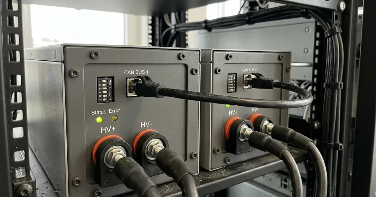
CANbus Daisy Chaining: In a multi-battery setup, batteries are typically connected in a "daisy chain" configuration for communication. This means one battery connects to the next, and the last battery connects to the inverter's BMS communication port. This serial connection allows the inverter to receive data from and send commands to all batteries in the chain. The communication cables used for this are standard RJ45 Ethernet cables. The specific pinout for Sunsynk's CANbus communication on the RJ45 connector is:
- CAN-H: Pin 4
- CAN-L: Pin 5
DIP Switch Addressing: To ensure each battery is uniquely identified within the daisy chain and that the master battery correctly communicates with the inverter, batteries are assigned addresses using onboard DIP (Dual In-line Package) switches. These small switches, usually found on the battery's casing, are set to specific ON/OFF positions to define each battery's role (master or slave) and its unique address.
Battery Balancing: In any multi-battery system, maintaining balance between individual battery units is critical for longevity and performance. An "unbalanced" system occurs when the "SOC (State of Charge) of each individual unit has a difference of >10%". This can lead to one battery being overstressed while another is underutilised. Key factors for maintaining balance include:
- Equal Cable Lengths: It is crucial that "all interconnecting battery cable sizes are the same length as cables of differing lengths can cause battery unbalances." This ensures uniform resistance and current distribution across all batteries.
- Regular Full Charges: The BMS requires periodic recalibration. This is achieved by "not reaching 100% SOC every 7-10 days for BMS recalibration." Ensuring your system regularly charges the batteries to full capacity allows the BMS to accurately recalibrate the SOC readings across the entire bank.
- Matching SOC for New Batteries: If you are "adding a new battery without matching SOC," it can immediately create an imbalance. New batteries should ideally be brought to a similar SOC as the existing bank before being connected.
For further troubleshooting of battery charging and communication issues, you can refer to the solarnevs guide on /za/guides/fixes/sunsynk-battery-not-charging-or-discharging.
Configuring BMS Communication and Battery Addressing
Proper configuration of your Sunsynk inverter and battery system is essential for reliable operation. This involves setting specific parameters on the inverter and correctly configuring the DIP switches on your batteries.
Inverter Battery Settings for BMS Communication
The following settings are found under the 'Battery Settings' menu on your Sunsynk inverter:
Setting Name | What it does | What to set it to |
|---|---|---|
Batt Type | Selects the type of battery connected to the inverter. | "Lithium" (for Sunsynk batteries) or "No Batt" (if no battery connected). |
Protocol | Defines the communication protocol between the inverter and the battery's BMS. | "0" for most batteries that communicate via CANbus. |
BMS_Err_Stop | Determines inverter behaviour if BMS communication fails. | When active, "if the battery BMS failed to communicate with inverter, the inverter will stop working and report fault." |
Parallel Bat1&2 | For high-voltage inverters with two battery ports, enables full discharge current when using both ports with one BMS. | "Enabled for full 100Amp discharge when utilizing both battery ports and 1 BMS on the inverter." Disabled if each port has its own battery and BMS. |
High-Voltage Battery Management Unit (BMU) Configuration
For high-voltage battery systems, the Battery Management Unit (BMU) on the battery rack itself requires configuration:
Setting Name | What it does | What to set it to |
|---|---|---|
BMU Number | This setting on the HV battery's display tells the BMU how many battery modules are connected in the rack. | "Adjust the BMU number accordingly (accessed on the BMU display by pressing the icon of a person and entering password 123) for this amount of batteries to ensure correct communications." |
The password to access the BMU display settings on high-voltage batteries is 123.
Battery DIP Switch Configuration
DIP switches are crucial for addressing individual batteries in a multi-battery system and defining master/slave roles. The specific configuration varies significantly by battery manufacturer and model.
- General Battery DIP Switches: "BMS communications can also be controlled via DIP switches on some models of battery. If your battery has DIP switches the installation guide/manual will likely have a DIP switch configuration you must follow for successful communications." Always consult your battery's installation manual for the correct settings.
- SSLB1 CATL Battery DIP Switches: For the SSLB1 CATL battery, if "any of the DIP switches are set to the Up, On, 1, position it will send the battery into fault" when not connected to an inverter or BMS interconnect cables. To resolve this, "Turn battery OFF, set ALL DIP switches to OFF/Down, then turn battery ON." Specific master/slave addressing for this model is detailed in the manufacturer's documentation, often with a diagram.
If you encounter fault codes like F13, F29, or F41 related to parallel inverter operation, a system restart may be required. For more details on these and other fault codes, refer to the solarnevs guide on /za/guides/fixes/sunsynk-fault-codes-explained. For general inverter paralleling, consult /za/guides/fixes/paralleling-sunsynk-inverters.
What you can change yourself, and what you cannot
Understanding the boundary between user-adjustable settings and those requiring a registered professional is crucial for safety and compliance in South Africa.
What you can change yourself: As a system owner, you can monitor your battery's State of Charge (SOC) to ensure it reaches 100% regularly for BMS recalibration. You can also visually inspect battery cable lengths to ensure they are equal, which helps prevent battery unbalances. If you are adding a new battery to an existing bank, you can ensure its SOC is matched to the existing batteries before connection.
What you cannot change yourself: Any physical wiring, including the CANbus daisy chain connections and battery power cables, must be installed or modified by a registered person. This includes ensuring "all interconnecting battery cable sizes are the same length" and that they are correctly terminated. Changing inverter settings like Protocol or BMS_Err_Stop should only be done by a qualified installer. Similarly, configuring battery DIP switches for master/slave addressing or adding/removing battery modules requires professional expertise. Incorrect configuration can lead to system malfunction, damage to equipment, or safety hazards. In South Africa, such work requires a Certificate of Compliance (CoC) issued by a qualified electrician, and unauthorised modifications can invalidate your system's CoC and warranty.
If your high-voltage battery's BMU screen shows a different voltage than the inverter, or if the voltage fluctuates rapidly, it could indicate incorrect battery connections or BMS communication issues, which requires professional inspection.
What the published sources do not tell you
While Sunsynk provides valuable information, certain specifics regarding multi-tower high-voltage battery synchronization and BMS communication are not fully detailed in the publicly available documentation:
- Comprehensive RJ45 Pinout Diagrams: the manufacturer documentation explicitly states the CAN-H (pin 4) and CAN-L (pin 5) for RJ45, but it does not provide detailed pinout diagrams for all Sunsynk inverter models and battery models beyond this general statement. Specific diagrams for different models could clarify wiring for various setups.
- Detailed DIP Switch Configurations for All Battery Models: While the importance of DIP switches for addressing is highlighted, and a specific fault condition for the SSLB1 CATL battery is mentioned, detailed ON/OFF configurations for all Sunsynk-compatible battery models are not provided. Users are directed to consult their battery's installation guide, implying these are battery-specific rather than universal Sunsynk guidelines.
- In-depth Balancing Protocols: Beyond the general advice of ensuring equal cable lengths and regular 100% SOC charges for BMS recalibration, the manufacturer documentation does not delve into more technical "balancing protocols" or internal BMS algorithms that manage cell-level balancing.
- Multi-Tower Synchronization with Native 3-Phase Inverters: Commercial microgrid installations frequently require multi-tower HV battery parallel synchronization with Sunsynk 3-phase inverters. While the general principles of daisy-chaining, addressing, and CANbus communication apply, detailed wiring schematics for native 3-phase high-voltage units should be confirmed with official application engineering notes.
- Battery Compatibility Document for RS485 Protocols: the manufacturer documentation mentions that "most that communicate via CAN are protocol 0 and batteries that communicate via RS485 may change (check the battery compatibility document for the list)," but this specific "battery compatibility document" is not provided in the corpus.
Frequently asked questions
What is CANbus daisy chaining for Sunsynk batteries?
CANbus daisy chaining connects multiple Sunsynk batteries in sequence using RJ45 cables for communication with the inverter's Battery Management System (BMS). This allows the inverter to monitor and control the entire battery bank. The CAN-H signal uses pin 4 and CAN-L uses pin 5 on the RJ45 connector.
How do I address multiple Sunsynk batteries in a multi-tower setup?
Multiple Sunsynk batteries in a multi-tower setup are typically addressed using DIP switches on each battery. These switches configure the master and slave roles, ensuring proper communication and identification within the battery bank. The specific DIP switch configuration varies by battery model and should be followed from the manufacturer's installation guide.
What causes unbalanced batteries in a multi-battery system and how is it fixed?
Unbalanced batteries, where the State of Charge (SOC) difference exceeds 10% between units, can be caused by unequal interconnecting cable lengths or insufficient charging that prevents batteries from reaching 100% SOC every 7 to 10 days for BMS recalibration. Ensuring all battery cables are the same length and allowing regular full charges helps maintain balance.
Can Sunsynk inverters synchronize with multiple high-voltage battery towers?
Sunsynk inverters can manage multiple high-voltage battery units through their Battery Management System (BMS) communication. For multi-tower high-voltage battery synchronization, especially with native 3-phase inverters, specific configuration steps are required, including adjusting the Battery Management Unit (BMU) number to match the number of connected batteries.
What is the password for the Sunsynk high-voltage battery BMU?
The password required to access certain data on the Sunsynk high-voltage series battery BMU is 123. This password is used to adjust settings like the BMU number, which ensures correct communication with the inverter.
References
- Sunsynk Support: Hybrid Inverter and Separate Battery vs All-in-One — accessed 27 August 2026
- Sunsynk Support: Paralleling Low Voltage Inverters — accessed 27 August 2026
- Sunsynk Support: Low Voltage Battery Specification — accessed 27 August 2026
- Sunsynk Support: SSLB1 DIP Switches — accessed 27 August 2026
- Sunsynk Support: BMS Communications — accessed 27 August 2026
- Sunsynk Support: Unbalanced Batteries — accessed 27 August 2026
- Sunsynk Support: High Voltage Battery SOC Suddenly Increases or Decreases — accessed 27 August 2026
- Sunsynk Support: High Voltage BMU Screen Shows a Different Voltage to the Inverter Battery Voltage — accessed 27 August 2026
- Sunsynk Support: HV Batteries - Adding a New Battery Module to an Existing Rack — accessed 27 August 2026
- Sunsynk Support: HV Battery BMU Password — accessed 27 August 2026
- Sunsynk Support: Classic/Acure/Elite - Understanding the Battery Settings — accessed 27 August 2026
- Sunsynk Support: Classic/Acure/Elite - High Voltage Battery Settings — accessed 27 August 2026
- Sunsynk Support: Classic/Acure/Elite - Three Single Phase Inverters on a Three Phase Supply — accessed 27 August 2026
- Sunsynk Support: SSLB1 CATL Battery Measures 16V — accessed 27 August 2026
Related guides
More from inverter errors & fixes.