Sunsynk Three-Phase High-Voltage Commercial Hybrid Inverter Setup Guide
Updated 8 September 2026 · By SolarNevs Research Desk, Dealer surveys + verified sources · 10 sources · Method ↗
Key Takeaways
- Sunsynk 50kW High Voltage inverters can be paralleled up to 10 units for increased capacity.
- Each 50kW High Voltage inverter in a parallel setup requires its own dedicated high-voltage battery pack.
- Correct CT clamp wiring and phase rotation are critical for three-phase systems to prevent issues like increased load during export.
- Grid-protection and export settings are for registered professionals; owner-facing settings like work modes and timers can be adjusted by the user.
- Always follow the inverter restart procedure (PV off, AC off, Inverter off, Battery off, wait 2 minutes, Battery on, Inverter on, AC on, PV on) for safe operation.
Setting Up Your Sunsynk 50kW Three-Phase High-Voltage Hybrid Inverter
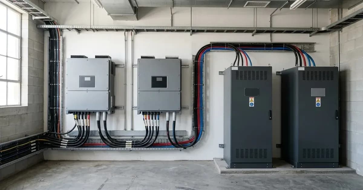
The Sunsynk 50kW High Voltage hybrid inverter (model SUN-50K-SG01HP3) is designed for commercial and large-scale residential applications requiring significant power output and high-voltage battery integration. This guide focuses on the installation and configuration aspects specific to these three-phase, high-voltage units, including CT clamp wiring, high-voltage battery connections, and parallel operation.
Understanding Three-Phase and High-Voltage Operation
Three-phase inverters manage power across three alternating current (AC) phases, common in commercial and industrial settings. High-voltage (HV) inverters operate with battery banks at higher DC voltages, typically leading to lower currents for the same power, which can reduce cable losses and simplify wiring for large battery capacities.
For three-phase systems, correct phase rotation is essential. If the L1, L2, and L3 cables are not in the correct order, you may observe the load increasing when the system is exporting power. This indicates an issue with the phase sequence.
Critical Settings and Procedures for Sunsynk 50kW High-Voltage Inverters
The following table outlines key settings and procedures for the Sunsynk 50kW High Voltage hybrid inverter, particularly for three-phase and parallel installations.
Setting / Procedure | What it does | What to set it to / How to perform | Product / Context |
|---|---|---|---|
Max. number of Inverters in parallel | Defines the maximum number of 50kW High Voltage inverters that can operate together. | 10 | Sunsynk 50kW Hybrid Inverter (High Voltage) |
Battery connection for parallel operation | Specifies how batteries are connected in a multi-inverter setup. | Each 50kW Inverter MUST have its own HV Battery pack. | Sunsynk 50kW Hybrid Inverter (High Voltage) |
Parallel operation setup (cabling) | Describes the communication cabling for parallel units. | Link inverters using a patch cable from the Master inverter to the second inverter and so on. | Sunsynk 50kW Hybrid Inverter (High Voltage) |
Parallel operation setup (dip switches) | Configures the role of each inverter in a parallel cluster. | Set dip switches on for the master inverter. When more than 2 inverters are used, all dip switches should be on. | Sunsynk 50kW Hybrid Inverter (High Voltage) |
CT compatibility | Specifies the types of current transformers (CTs) supported. | 100A/50mA CTs or 300A/5A CTs | High Voltage series of inverters |
300A/5A CTs connection | Specifies the physical connection points for larger CTs. | Must be connected on the left-hand CT connections in the inverter. | High Voltage series of inverters |
100A/50mA CTs connection | Specifies the physical connection points for standard CTs. | Must be connected in the right-hand side. | High Voltage series of inverters |
CT ratio for 300A/5A CTs | The ratio setting for larger CTs. | 6000:1 | High Voltage series of inverters |
CT ratio for 100A/50mA CTs | The standard ratio setting for smaller CTs. | 2000:1 | High Voltage series of inverters |
CT Clamp Connections (Three-Phase Inverters) | Defines the pin assignments for three-phase CT wiring. | Phase 1: pin 3 and pin 4; Phase 2: pin 5 and pin 6; Phase 3: pin 7 and pin 8 | Three-Phase Inverters |
CT Clamp Direction | Ensures correct current measurement. | The arrow should be pointing towards the inverter. | General CT Clamp Installation |
CT Clamp Cable Length | Recommended maximum length for CT cables. | Ideally no more than 10 metres, can be extended up to 15 metres in some circumstances. | General CT Clamp Installation |
CT Clamp Cable Extension | Guidelines for extending CT cables. | Must be copper, equal or thicker to existing CT cables; use twisted pair (CAT5/6) to reduce resistance/interference. | General CT Clamp Installation |
CT Clamp Interference | Recommended clearance from other electrical components. | Clearance of 50-100cm from other CTs; not run closely paralleled to AC cables, not in same trunking. | General CT Clamp Installation |
CT Ratio Setting | Location for adjusting the CT ratio. | Set in 'Advanced Settings'. | General CT Clamp Configuration |
Incorrect phase rotation (symptom) | Indicates a wiring error in three-phase systems. | If export causes load to increase, correct L1, L2, L3 cable order; test phase readings with clamp meter. | Three-Phase Inverters |
Earth-Neutral Bond (Parallel Inverters) | Specifies how the E-N bond is handled in parallel systems. | The Earth-Neutral bond relay should only be connected to the Master inverter. | Parallel Installation |
Earth-Neutral Bond (Three-Phase Units with RCD Generator) | Built-in E-N bond switching for three-phase units. | Enable 'Signal-Island Mode' in inverter settings. | Three-Phase Inverters with RCD Generator |
Wind Turbine Integration (High-Voltage Inverter) | Firmware requirement for wind turbine connection. | Inverter must be on specific firmware: LCD: E04B, microcontroller firmware: 1110. Max wind turbine input voltage: 850V MAX. | High-Voltage Inverter |
Parallel Bat1&2 | Setting for using both battery ports with a single BMS. | Must be enabled for full 100 Amp discharge when utilising both battery ports with 1 BMS on the inverter. | High-Voltage Battery Settings |
Parallel Bat1&Bat2 | Setting for using separate batteries on each port. | Must NOT be enabled when utilising each port with its own battery (each input independently connected). | High-Voltage Battery Settings |
Eastron Meter Settings (SDM630MCT) | Password for accessing Eastron meter setup. | Password: 1000 | External Meter Configuration |
Inverter Restart Procedure | Safe shutdown and startup sequence. |
| General Inverter |
Parallel Operation of Sunsynk 50kW High-Voltage Inverters
The Sunsynk 50kW High Voltage inverter supports parallel operation, allowing you to combine up to 10 units for increased power capacity. When setting up a parallel system:
- Dedicated Battery Packs: Each 50kW Inverter MUST have its own high-voltage battery pack. Unlike low-voltage systems where batteries can be shared, high-voltage batteries must be connected separately to each HV hybrid inverter.
- Communication Cabling: Link the 50kW Inverters using a patch cable. This cable connects from the Master inverter to the second inverter, and then to subsequent inverters in the chain.
- Dip Switch Configuration: Set the dip switches to 'on' for the master inverter. If you are paralleling more than two inverters, ensure all dip switches are set to 'on'.
- Earth-Neutral Bond: In a parallel installation, the Earth-Neutral bond relay should only be connected to the Master inverter.
For more detailed information on paralleling, refer to our guide on /za/guides/fixes/paralleling-sunsynk-inverters.
CT Clamp Installation and Configuration
Accurate current transformer (CT) readings are vital for the inverter's operation, especially in three-phase commercial setups.
- Placement: The CT clamp should always be placed on the live incomer of the property, before any Henley blocks or distribution boards.
- Direction: The arrow on the CT clamp should always point towards the inverter.
- Three-Phase Wiring: For three-phase inverters, connect the CT tails as follows:
- Phase 1: pin 3 and pin 4
- Phase 2: pin 5 and pin 6
- Phase 3: pin 7 and pin 8
- CT Types and Ratios: The High Voltage series of inverters are compatible with 100A/50mA CTs or 300A/5A CTs.
- For 300A/5A CTs, connect them to the left-hand CT connections and set the CT ratio to 6000:1.
- For 100A/50mA CTs, connect them to the right-hand side and the standard 2000:1 CT ratio applies.
- Cable Length and Extension: The cable length between the inverter and the CT clamp should ideally be no more than 10 metres, though it can be extended up to 15 metres. If extending, the cable must be copper, equal to or thicker than the existing CT cables, and a twisted pair (e.g., CAT5/6) should be used to reduce resistance and interference.
- Interference: Maintain a clearance of 50-100cm from other CTs and avoid running CT cables closely parallel to AC cables or in the same trunking to prevent interference.
- Verification: To check if the CT coil is reading correctly, ensure the HM or CT Reading on the AC Load dial is a positive reading when importing from the grid.
- Eastron Meters: If using an Eastron SDM630MCT meter for three-phase systems, the password to enter setup mode is 1000.
For more information on CT clamp issues, see our guide on /za/guides/fixes/sunsynk-ct-coil-wrong-readings.
What you can change yourself, and what you cannot
As a system owner, you can typically adjust settings related to your energy usage patterns, such as work modes, battery State of Charge (SOC) targets, and timer schedules. These settings allow you to optimise your system for load-shedding or specific energy demands.
However, critical grid-protection settings, export limits, and any modifications to the physical wiring (AC tails, PV strings, battery connections) must only be performed by a registered and qualified electrical professional. In South Africa, such work requires a Certificate of Compliance (CoC) to ensure safety and adherence to NRS 097-2-1 grid interconnection standards. Incorrectly altering these settings can void warranties, breach your connection agreement with Eskom or your municipality, and pose significant safety risks.
What the published sources do not tell you
While the Sunsynk documentation provides valuable guidance, there are a few areas where specific details for the South African context or commercial installations are not explicitly covered:
- NRS 097 Compliance for 50kW Three-Phase HV Inverter: The provided sources confirm NRS 097-2-1 compliance for some single-phase models, but do not explicitly state it for the 50kW three-phase high-voltage commercial inverter (SUN-50K-SG01HP3). Installers should verify the specific inverter's certification against local grid codes.
- HV Battery DC Voltage Window (160V-800V): While a maximum wind turbine input voltage of 850V is mentioned for high-voltage inverters, the precise operating DC voltage window for high-voltage batteries (e.g., 160V-800V) is not explicitly detailed in the provided support articles. This information is typically found in specific battery datasheets or the inverter's full manual.
- Detailed Parallel Operation Settings: The documentation for paralleling 50kW units refers to a "Manual on installing the 50kW unit" for specific parameters and settings, which was not available in the manufacturer documentation. This suggests that some granular configuration details for large parallel systems may require consulting the full product manual.
- UK Grid Rules: The Sunsynk documentation frequently references UK grid regulations like G98/G99 for voltage and frequency limits (e.g., 216.2V-253V). These are specific to the UK and do not apply in South Africa, where the standard supply is 230V/50Hz and governed by NRS 097-2-1. Always adhere to South African standards and consult with a qualified local installer.
Frequently asked questions
How many Sunsynk 50kW High Voltage inverters can be paralleled?
You can parallel a maximum of 10 Sunsynk 50kW High Voltage inverters. Each inverter in a parallel setup must have its own high-voltage battery pack connected separately.
What is the correct CT clamp wiring for a three-phase Sunsynk inverter?
For three-phase inverters, the CT tails for Phase 1 must be in pin 3 and pin 4, Phase 2 in pin 5 and pin 6, and Phase 3 in pin 7 and pin 8. The CT clamp's arrow should point towards the inverter.
What is the maximum wind turbine input voltage for a Sunsynk high-voltage inverter?
The maximum wind turbine input voltage for a Sunsynk high-voltage inverter can be 850V MAX. The inverter must be on specific firmware versions: LCD E04B and microcontroller firmware version 1110.
How do I resolve incorrect phase rotation on a three-phase Sunsynk inverter?
If your three-phase inverter shows increased load when exporting, it may be due to incorrect phase rotation. Correct the L1, L2, and L3 cable order and test phase readings with a clamp meter.
What CT clamp types are compatible with Sunsynk High Voltage series inverters?
The Sunsynk High Voltage series of inverters are compatible with 100A/50mA CTs or 300A/5A CTs. The 300A/5A CTs connect to the left-hand CT connections, while the 100A/50mA CTs connect to the right-hand side.
References
- Sunsynk Support: Paralleling High Voltage Inverters — accessed 27 August 2026
- Sunsynk Support: CT Clamp Guide — accessed 27 August 2026
- Sunsynk Support: Three-Phase Inverters Load Increases When Exporting — accessed 27 August 2026
- Sunsynk Support: Connecting a Wind Turbine to a High Voltage Inverter — accessed 27 August 2026
- Sunsynk Support: Inverter Restart Procedure — accessed 27 August 2026
- Sunsynk Support: Earth-Neutral Bond — accessed 27 August 2026
- Sunsynk Support: Classic/Elite/Acure Generator Connections — accessed 27 August 2026
- Sunsynk Support: Classic/Acure/Elite Using a Generator with an RCD — accessed 27 August 2026
- Sunsynk Support: High Voltage Battery Settings — accessed 27 August 2026
- Sunsynk Support: Classic/Three-Phase Eastron Meter with Three-Phase Inverter — accessed 27 August 2026
Related guides
More from inverter errors & fixes.