Victron EM111 and EM112 Energy Meter Modbus Setup Guide
Updated 6 September 2026 · By SolarNevs Research Desk, Dealer surveys + verified sources · 1 source · Method ↗
Key Takeaways
- The Victron EM111 and EM112 are single-phase energy meters for direct measurement up to 100A.
- Always de-energize the AC supply and use insulated tools before wiring these meters.
- RS485 Modbus RTU communication requires correct wiring polarity and a 9600 baud rate for reliable operation with Victron GX devices.
- Incorrect wiring or configuration can lead to "Grid Meter Lost" alerts and system passthrough mode.
- If communication issues persist after checking wiring and settings, consult a qualified technician.
How do I set up a Victron EM111 or EM112 energy meter with Modbus?
Setting up a Victron EM111 (Part Number: REL200100000 / EM111DINAV81XS1X08) or EM112 (Part Number: REL200100000 / EM112DINAV01XS1X) energy meter involves physical wiring to your AC system and a Victron GX device, followed by configuration within Venus OS. These meters provide single-phase direct measurement up to 100A for grid metering, PV inverter monitoring, or AC load tracking in Victron Energy Storage Systems (ESS).
Diagnosis and Setup Steps
Follow these steps to correctly install and configure your EM111 or EM112 energy meter:
Step 1: Physical Installation and Wiring
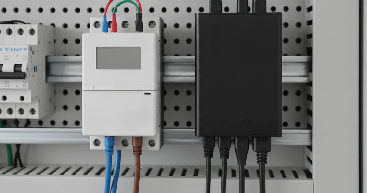
- Mount the Meter: Install the Carlo Gavazzi EM111 or EM112 onto a standard DIN rail within your distribution board.
- AC Power Wiring:
- Safety First: Always de-energize and lock out main AC supply breakers before installing the meter or terminating power conductors. Use appropriately rated insulated tools.
- Connect the AC power lines to the meter's power terminals. The EM111 and EM112 are designed for single-phase direct measurement up to 100A.
- Torque Terminals: With the circuit completely de-energized, torque all power screw terminals to manufacturer specifications using insulated tools. This prevents high-resistance thermal hotspots, especially under 100A load.
- RS485 Communication Wiring:
- Connect the RS485 A and B data lines from the EM111/EM112 to a Victron RS485 to USB interface cable (available in 1.8m or 5.0m lengths) or a Zigbee converter.
- Ensure correct polarity: RS485 A to A, and RS485 B to B. Reversing RS485 A/B data polarity will block communication with Venus OS.
- Plug the USB end of the interface cable into a USB port on your Victron GX device (e.g., Cerbo GX, Ekrano GX).
Step 2: Configure in Venus OS
- Power On: Re-energize the AC supply and power on your Victron GX device.
- Access Venus OS: Navigate to the device list on your GX device's display or through the Victron Remote Console.
- Identify Meter: The GX device should detect the connected EM111 or EM112.
- Configure Meter Role: In Venus OS, configure the meter's role. The Energy Meters are used in systems with a GX device to measure the output of a PV Inverter, a AC Genset or as a Grid Meter in an ESS installation. Select the appropriate role for your setup (e.g., Grid Meter, PV Inverter, Generator, or AC Load).
- Verify Communication: Check the device list and the relevant energy overview screens in Venus OS to ensure the meter is reporting data. The meters have a 1000ms register refresh rate, and the GX polling latency at 9600 baud is typically between 180ms and 250ms.
Cause/Fix Table
Symptom detail | Likely cause | Fix |
|---|---|---|
Venus OS displays "Grid Meter Lost" alert, system switches to passthrough. | RS485 Communication Timeout: RS485 polling fails or wiring latency exceeds timeout limits. | Check RS485 wiring for correct polarity (A to A, B to B). Ensure cable is securely connected to both meter and GX device. Verify Modbus address settings. |
Victron GX device does not identify the meter. | Baud Rate / Modbus Address Mismatch: Meter operating at baud rates other than 9600 baud or incorrect Modbus slave address. | Ensure the meter's baud rate is set to 9600. Verify the Modbus slave address matches the configuration expected by the GX device. |
Meter or wiring feels hot, or shows signs of thermal stress. | Exceeding the 100A continuous direct current limit; High-resistance hotspots due to loose terminals. | Ensure the AC load does not continuously exceed 100A. Re-torque all power screw terminals to manufacturer specifications. |
No data or incorrect data displayed in Venus OS. | Reversing RS485 A/B data polarity. | Correct the RS485 A/B wiring polarity. |
Intermittent communication or data drops. | Poor quality RS485 cable, excessive cable length, or electrical noise. | Use a shielded RS485 cable. Keep RS485 wiring separate from AC power lines. Consider using a shorter cable if possible. |
Modbus Communication Details and Configuration
The Victron EM111 and EM112 meters communicate using the RS485 Modbus RTU protocol. Understanding these details is crucial for reliable operation.
RS485 Protocol Basics
The EM111 and EM112 meters connect to a GX device via RS485 either through a wired connection via a RS485 to USB interface or wirelessly via a Zigbee to USB and Zigbee to RS485 converters. This serial communication standard allows multiple devices to share the same bus. For Victron systems, the standard baud rate for GX device polling is 9600 baud. The GX device latency (the time it takes to read at 9600 baud) is between 180 and 250ms.
Wiring and Polarity
Correct RS485 wiring involves connecting the A and B data lines. Reversing the RS485 A/B data polarity will block communication with Venus OS. Always double-check your connections to ensure A is connected to A and B to B between the meter and the RS485-to-USB adapter or Zigbee converter.
Meter Role in Venus OS
Once connected, the meter's function is defined within Venus OS. The Energy Meters are used in systems with a GX device to measure the output of a PV Inverter, a AC Genset or as a Grid Meter in an ESS installation. You can assign the meter one of these roles:
- Grid Meter: Measures energy flow to and from the utility grid.
- PV Inverter: Monitors the output of an AC PV inverter.
- Generator: Tracks energy from an AC generator.
- AC Load: Measures consumption of a specific AC load.
For more detailed wiring guidance on Victron components, you may refer to our guides on Victron SmartShunt and Lynx Distributor Wiring or Victron Lynx Distributor and Modular DC Busbar Wiring Guide.
Safety: Electrical Installation Guidelines
Working with AC power carries significant risks. Adhere strictly to these safety guidelines to prevent injury or damage to equipment.
- De-energize and Lock Out: Always de-energize and lock out main AC supply breakers before installing the meter or terminating power conductors. Verify zero voltage with a multimeter before touching any wires.
- Insulated Tools: Use appropriately rated insulated tools when making electrical connections inside distribution boards.
- Terminal Torque: After verifying the AC supply is locked out and de-energized, torque all power screw terminals to manufacturer specifications using insulated tools. Loose connections can lead to high-resistance thermal hotspots, which can cause overheating, fire, or equipment failure, especially under 100A load.
- Appropriate Wiring: Ensure all wiring is correctly sized for the maximum current (up to 100A) and properly insulated.
- Professional Installation: If you are unsure about any part of the installation process, consult a qualified electrician.
When to call a technician instead
While this guide covers common setup and troubleshooting steps, some issues require professional intervention. You should call a qualified technician if:
- You are uncomfortable working with high-voltage AC electricity.
- You encounter persistent "Grid Meter Lost" alerts or communication failures after verifying all wiring and settings.
- The meter or connected wiring shows signs of physical damage, overheating, or burning.
- You suspect internal damage to the meter, possibly from exceeding the 100A continuous direct current limit.
- Your Victron system is not behaving as expected, and you have exhausted all troubleshooting steps.
Attempting repairs or modifications beyond the scope of this guide may void your warranty and pose significant safety risks.
Add a battery at a surveyed price
Installers quote supply and fitting of the battery on this page for your existing or new system.
How this pays for the site: installers pay SolarNevs a fixed introduction fee when we pass them a genuine enquiry. They cannot pay to appear higher, and our surveyed prices are published before any introduction. You can also take our dated price tables straight to any installer.
Frequently asked questions
What are the Victron EM111 and EM112 energy meters used for?
The EM111 (Part Number: REL200100000 / EM111DINAV81XS1X08) and EM112 (Part Number: REL200100000 / EM112DINAV01XS1X) are single-phase energy meters designed for Victron Energy Storage Systems (ESS). They measure up to 100A directly for grid metering, PV inverter monitoring, or AC load tracking.
How do EM111 and EM112 meters communicate with a Victron GX device?
These meters communicate via RS485 Modbus RTU. This can be a wired connection using a Victron RS485 to USB interface cable or wirelessly through Zigbee converters.
What happens if the RS485 communication fails?
If RS485 polling fails or wiring latency exceeds timeout limits, Venus OS will display a 'Grid Meter Lost' alert. The ESS system then switches into a safe passthrough mode.
What is the maximum current the EM111 and EM112 can measure?
Both the EM111 and EM112 are designed for single-phase direct measurement up to 100A. Exceeding this continuous direct current limit can cause internal shunt thermal damage.
What is the refresh rate for data from these meters?
The EM111 and EM112 meters have a 1000ms register refresh rate, providing real-time data for monitoring.
References
- Victron Energy Meters Selection Guide Datasheet — accessed 23 August 2026
Related guides
More from what to buy — and how not to get cheated.